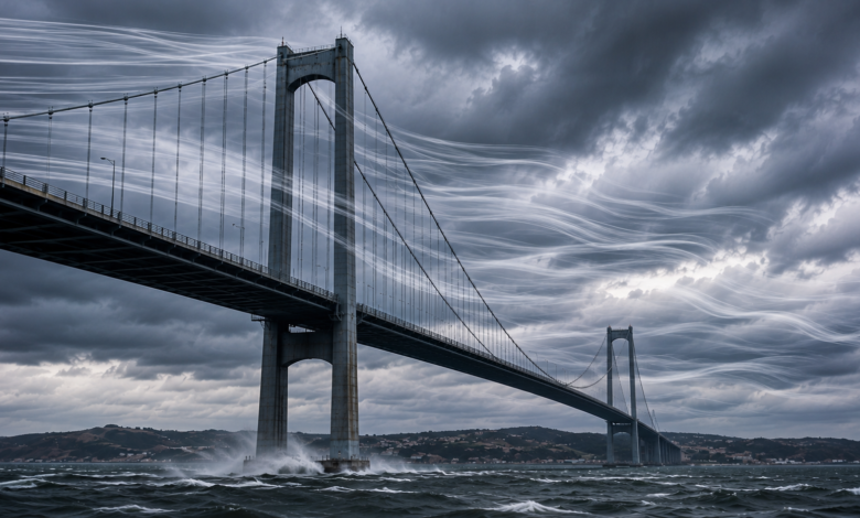
Bridge Aerodynamics: 5 Powerful Solutions That Prevent Collapse
Bridge aerodynamics is the engineering discipline that determines whether a long-span structure remains stable under wind loads or tears itself apart through self-excited oscillation. It governs deck shape, damping hardware, and testing protocols on every major suspension and cable-stayed crossing built since 1940. On spans beyond 1,000 metres, wind load engineering, not traffic or seismic loading, is usually the governing design case.
Technical Snapshot: Core Engineering Parameters
| Parameter | Detail |
| Governing failure modes | Aeroelastic flutter, vortex-induced vibration, buffeting, galloping |
| Critical flutter speed benchmark (modern decks) | Above 78 m/s (280 km/h) for streamlined and truss-stiffened girders |
| Reference failure case | Tacoma Narrows Bridge collapsed on 7 November 1940 at roughly 19 m/s (68 km/h) |
| Design wind speed, Akashi Kaikyo Bridge | 286 km/h (178 mph) |
| Design wind resistance, Millau Viaduct deck | Up to 225 km/h (140 mph) |
| Primary mitigation tools | Streamlined box girders, slotted decks, guide vanes, tuned mass dampers, wind tunnel validation |
Every landmark bridge built since Tacoma Narrows carries the fingerprint of bridge aerodynamics in its cross-section, its damping hardware, and its wind tunnel data. Getting bridge aerodynamics right separates a structure that stands for a century from one that becomes a case study.
Introduction: Wind, the Silent Force Every Bridge Engineer Must Outdesign
Wind does not simply push against a bridge deck. It separates around sharp edges, forms vortices, and can lock onto the structure’s natural frequency, feeding energy into the span with each oscillation. This is the core problem that bridge aerodynamics exists to solve, and it sits at the centre of the engineering story behind the world’s tallest bridge structures, where extreme height multiplies wind exposure and turns aerodynamic bridge design from a secondary consideration into a governing constraint.
Wind load engineering has matured into its own specialism precisely because static structural analysis cannot predict what happens once a flexible deck interacts dynamically with moving air. A span can satisfy every strength calculation on paper and still fail catastrophically once aerodynamic instability takes hold. This article sets out five solutions that modern bridge wind resistance depends on, each developed through decades of wind tunnel research, field monitoring, and, in the case of the Tacoma Narrows Bridge, a hard lesson learned through collapse. Understanding bridge aerodynamics and collapse prevention together enables engineers to design for the worst-case storm, not merely the average one.
Understanding Wind-Induced Bridge Vibration
Before the fixes, it helps to understand what engineers are fixing. Wind-induced bridge vibration is not one phenomenon but several distinct mechanisms, each with its own trigger and countermeasure. Confusing them, as early twentieth-century engineers often did, is how Tacoma Narrows ended up under-designed for a threat nobody had properly categorised.
Vortex Shedding and Flutter
When wind meets a blunt deck edge, it cannot follow the surface smoothly. It separates instead, shedding vortices alternately from the top and bottom edges. If that shedding frequency matches the deck’s natural frequency, vortex-induced vibration follows: a persistent, self-limiting oscillation that fatigues connections long before it threatens collapse outright. Flutter is the more dangerous relative, occurring when a deck’s own twisting motion changes the aerodynamic forces acting on it in a way that reinforces rather than resists the twist, a feedback loop that pumps more energy into the structure with every cycle.
Wind-Induced Failure Modes at a Glance
| Failure Mode | Trigger Mechanism | Typical Onset | Structural Consequence |
| Vortex-induced vibration | Shedding frequency locks onto the deck’s natural frequency | Moderate, steady wind speeds | Self-limiting oscillation; fatigues connections over time |
| Aeroelastic flutter | Deck motion itself alters aerodynamic forces (negative damping) | Sustained wind above critical flutter speed | Unbounded amplitude growth; can lead to structural collapse |
| Buffeting | Random atmospheric turbulence acting on the deck | Present in most wind conditions | Cumulative fatigue on cables, hangers and joints |
| Galloping | Cross-sectional asymmetry (e.g., ice- or rivulet-coated cables) | Moderate wind combined with rain or ice accretion | Large-amplitude, low-frequency cable oscillation |
The Tacoma Narrows Bridge Aerodynamic Failure
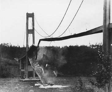
The 1940 Tacoma Narrows Bridge aerodynamic failure remains the definitive illustration of how wind load affects bridge design when aerodynamics is treated as an afterthought. Its solid plate girders, rather than an open truss, gave wind nowhere to pass through, and once torsional flutter began at a sustained wind speed above roughly 56 km/h, the oscillation grew without bound until the suspender cables snapped and the deck dropped into Puget Sound.
Investigators, including Theodore von Kármán, confirmed the mechanism as self-excited aeroelastic instability rather than simple mechanical resonance, a distinction that still shapes how engineers analyse wind-induced vibration in suspension bridges today. Later research into the vortex formation and drift process behind the collapse built on that finding, replacing guesswork with quantifiable flutter derivatives that now feed directly into design software.
Solution 1: Streamlined and Slotted Deck Aerodynamics
The most effective way to prevent wind-induced bridge vibration is to stop the deck from generating destructive aerodynamic forces in the first place. Cross-section shape governs how cleanly air flows past the structure, and this is where bridge deck aerodynamics research has concentrated its heaviest effort since the 1940s.
Streamlined Box Girder Profiles
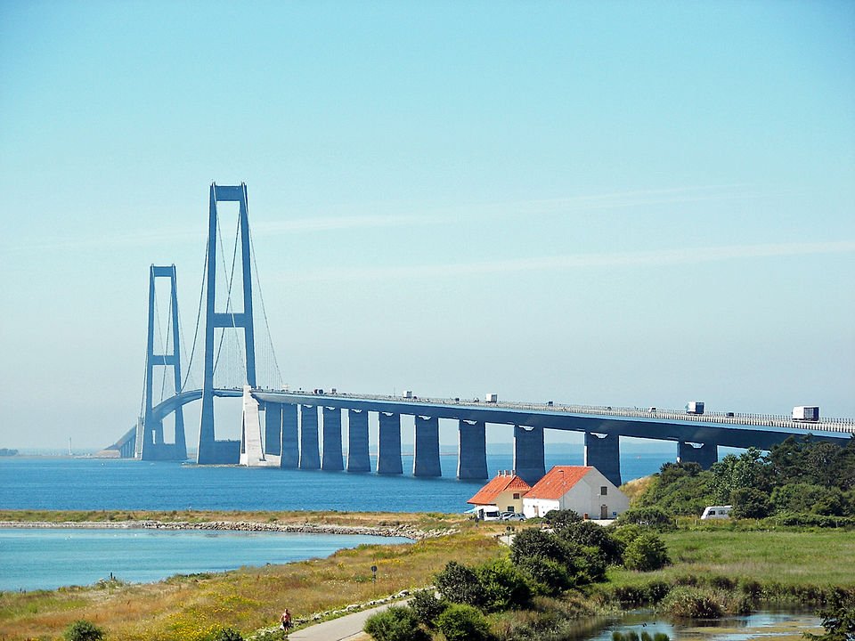
Modern long-span bridges typically use a shallow, tapered box girder shaped as an aircraft wing turned on its side, letting wind slip past rather than slam into a flat face. The Great Belt East Bridge team tested 16 trapezoidal box sections in the wind tunnel before settling on a profile that comfortably pushed the critical flutter speed above regional design thresholds. This streamlined approach to aerodynamic design of bridge decks helps explain why cable-stayed spans have become the fastest-growing bridge format worldwide, where deck geometry drives much of the format’s structural efficiency.
Slotted and Twin-Box Configurations
On the longest spans, engineers split the deck into two box girders connected by cross-beams, leaving a central slot open to the air. This configuration, used on China’s Xihoumen Bridge and studied extensively for Stonecutters Bridge, lets wind pass through the gap rather than build up pressure across a solid deck. Stonecutters adopted a 14.3-metre clear separation between its twin boxes specifically to push the critical one-minute flutter speed above 95 metres per second, a wide margin over any storm the crossing is likely to face.
Truss-Stiffened Decks for High-Turbulence Sites
Not every site is suited to a streamlined box girder. Where torsional stiffness or construction access dominates, engineers fall back on open steel truss decks, a structural choice that comes down to how truss systems distribute wind and gravity loads differently from beam and arch designs.
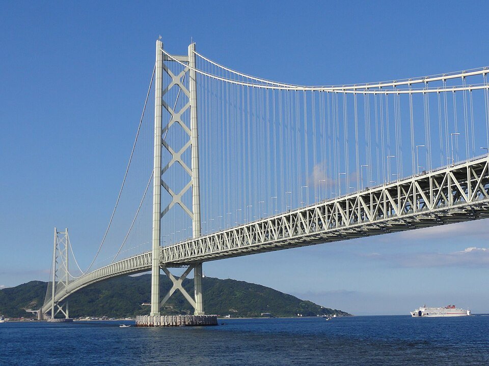
The Akashi Kaikyo Bridge, spanning the turbulent Akashi Strait with a 1,991-metre main span, uses a truss-stiffened girder precisely because its open lattice lets wind blow through rather than around, trading some aerodynamic elegance for the torsional stiffness a strait crossing demands. This trade-off is routine in bridge deck aerodynamics decision-making on sites where turbulence, not steady laminar flow, defines the wind climate, a challenge shared by the engineering demands of undersea tunnels and sea crossings elsewhere in Construction Frontier’s tunnels’ megastructure coverage.
Solution 2: Wind Fairings, Guide Vanes and Edge Deflectors
Even a well-streamlined deck benefits from smaller aerodynamic add-ons that fine-tune airflow at the edges, where vortex formation is most sensitive to geometry. These devices are cheap relative to the deck itself but deliver disproportionate gains in bridge wind resistance, and they form a core part of any credible bridge collapse-prevention strategy for a long-span crossing.
Fairing Angle and Vortex Suppression
Wind fairings are angled panels fitted to the leading and trailing edges of a box girder. Research on closed-box girders has found that a fairing angle of around 50 degrees yields the most balanced wake, producing a single coherent vortex rather than the chaotic pattern that drives resonant oscillation. Sharper fairings paired with slender railings have also been shown to markedly improve vortex-induced vibration performance, an insight now standard in aerodynamic bridge design for new long-span crossings. This kind of detailing shows why the aerodynamic design of bridge decks has become as much about millimetre-scale edge geometry as it is about the overall cross-section.
Guide Vanes and Wind Screens
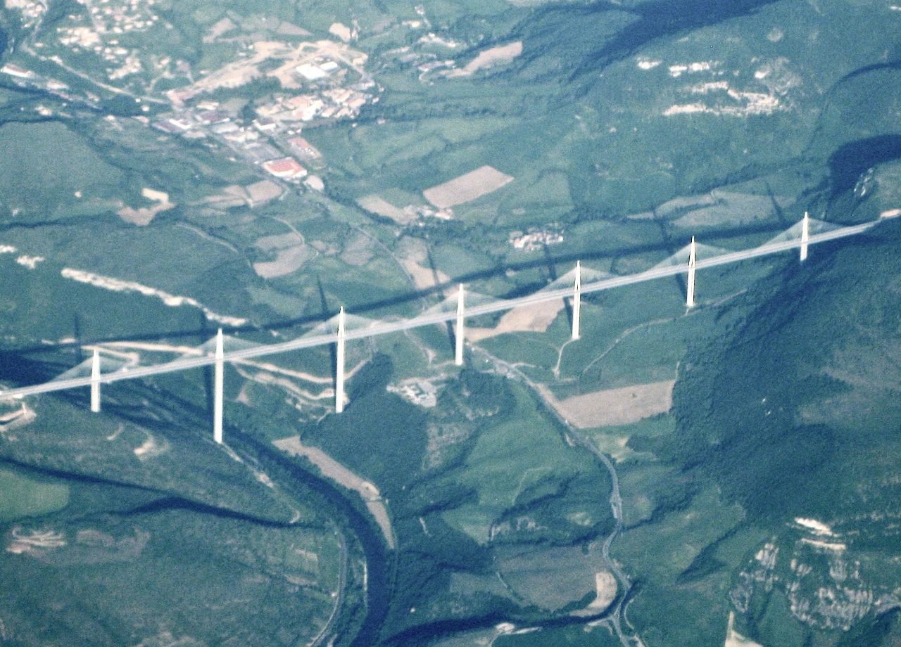
Guide vanes, small fixed fins mounted under the girder, redirect airflow to stop vortices from forming in the pocket beneath the deck. Testing on Great Belt Bridge models confirmed that vortices visible beneath an unmodified deck vanished once guide vanes were installed. The Millau Viaduct, whose inverse-aerofoil deck presses down onto its pylons under strong wind rather than lifting, adds curved transparent windscreens roughly three metres high along both edges, not to eliminate crosswind but to reduce it to the level a driver would feel on the approach roads on either side of the gorge.
Solution 3: Tuned Mass Dampers and Structural Damping
Shaping the deck reduces the forces wind can generate. Damping systems deal with what happens once those forces are already in motion, absorbing energy before it can build toward the runaway condition that destroyed Tacoma Narrows.
How Tuned Mass Dampers Counter Oscillation
A tuned mass damper is a large weight, often tens of tonnes, mounted on springs or pendulums and calibrated to oscillate at the same frequency as the structure it protects, but out of phase, cancelling a meaningful share of the motion before it amplifies further. This is a mechanical answer to a problem that shaping alone cannot fully solve, especially where architectural constraints limit how streamlined a deck can be.
Damper Placement and Combined Loading
The Akashi Kaikyo Bridge houses twenty tuned mass dampers in each tower, tuned to the structure’s resonance frequency to counter both wind sway and seismic motion, given the strait’s exposure to typhoons and earthquakes alike. The Millau Viaduct integrates dampers into its piers and deck for the same reason. This dual function against overlapping hazards shows up repeatedly in how engineers design bridges for the world’s harshest wind and seismic environments, where crossings built across straits and fault zones must satisfy wind and seismic load cases within a single damping strategy rather than treating them as separate disciplines.
Tuned Mass Damper Applications on Landmark Bridges
| Bridge | Damper Type | Location | Dual Function |
| Akashi Kaikyo Bridge | Tuned mass dampers, 20 per tower | Tower structures | Wind sway and seismic motion (up to magnitude 8.5) |
| Millau Viaduct | Tuned mass dampers integrated into piers and deck | Piers and box-girder deck | Dynamic wind response on a slender, low-mass deck |
| Bronx–Whitestone Bridge (retrofit) | Stiffening trusses, later aerodynamic fairings | Both sides of the deck | Retrofit response to a Tacoma Narrows-era design flaw |
Further Reading: Extreme Environment Bridge Engineering: 4 Proven Global Solutions
Solution 4: Wind Tunnel Testing and Aeroelastic Modelling
None of the deck shapes, fairings, or dampers above would exist in their current form without a testing regime capable of catching instability before construction, not after. Wind tunnel testing translates bridge aerodynamics from theory into a verifiable design output, a standard practice on every major long-span crossing since the Tacoma Narrows Bridge forced the profession to take wind seriously.
Section Models and Full-Aeroelastic Models
Engineers typically begin with scaled section models, short lengths of deck mounted on springs that replicate stiffness and mass, tested across a range of wind speeds and angles of attack to locate vortex-induced vibration and flutter onset. For the most demanding sites, testing progresses to full aeroelastic models spanning the entire bridge length at reduced scale. The Akashi Kaikyo Bridge team ran a full-model test in one of the longest wind tunnels built for the purpose, since its span length and exposure to typhoon-strength gusts left no room for extrapolating from partial data.
Computational Fluid Dynamics and Critical Flutter Speed
Computational fluid dynamics now runs alongside physical wind tunnel work, modelling airflow separation around candidate deck sections before a single physical model is built, narrowing the field to the strongest candidates for costlier physical testing. Every programme produces one defining number: the critical flutter wind speed at which self-excited oscillation stops being self-limiting and starts growing without bound. Engineers set the design wind speed with a substantial margin below that threshold, a discipline traceable directly to lessons from the Tacoma Narrows Bridge aerodynamic failure, which made critical flutter speed a mandatory calculation on every long-span bridge built since.
Wind Tunnel and Computational Testing Methods Compared
| Testing Method | Scale | What It Identifies | Typical Stage |
| Section model wind tunnel test | Short deck length on springs, 1:50 to 1:80 scale | Vortex-induced vibration and initial flutter onset | Concept and preliminary design |
| Full-aeroelastic model test | Entire span at reduced scale, typically 1:100 to 1:200 | Whole-structure dynamic response, including tower interaction | Detailed design validation |
| Computational fluid dynamics (CFD) | Digital simulation, no physical model | Airflow separation and vortex drift across many candidate sections | Early screening before physical testing |
Solution 5: Structural Configuration and Span Selection
The final layer of bridge collapse prevention occurs before deck design even begins, in the choice of structural system. Different bridge types carry different aerodynamic risk profiles, and matching the system to a site’s wind climate matters as much as any individual feature added afterward. This is wind load engineering at its most fundamental: choosing a structural form that starts from a position of bridge wind resistance rather than trying to correct for a poor choice later.
Matching Deck Type to Site Wind Conditions
A streamlined box girder suits sites with predictable, largely laminar flow, but a strait exposed to gusting, turbulent winds may favour a truss-stiffened deck precisely because its open structure resists the coherent vortex formation that turbulence can otherwise disrupt into more dangerous patterns. This site-specific decision-making underpins the core stability principles behind long-span suspension bridge design, where deck and cable configuration are treated as inseparable from the wind environment a crossing must survive.
Cable Configuration and Rain-Wind Vibration
A cable-and-stay arrangement has its own aerodynamic dimension. Long inclined stays are prone to rain-wind-induced vibration, where water rivulets forming on the cable surface under light rain and wind change its effective shape enough to trigger galloping-type oscillation. Millau Viaduct’s stays use spirally patterned polyethylene sheathing specifically to disrupt rivulet formation, a small manufacturing detail with an outsized effect on wind-induced bridge vibration in cable-stayed structures. Engineering bridges to resist wind forces this way, at cable level rather than deck level alone, closes a gap that shaping the deck cannot cover.
Further Reading: Suspension Bridge Design: 5 Proven Principles for Structural Stability
Technical Block: Applying Bridge Aerodynamics in Practice
The principles above translate into concrete design thresholds on real structures. The breakdown below sets out how landmark bridges apply principles of bridge aerodynamics to quantify wind resistance, and how older structures are monitored for the risk of wind-induced bridge vibration once in service.
1. Design Wind Speed Thresholds Across Landmark Bridges
Design Wind Thresholds and Solutions for Bridges
| Bridge | Design Wind Threshold | Primary Aerodynamic Solution |
| Akashi Kaikyo Bridge | 286 km/h (178 mph) | Truss-stiffened girder, tower-mounted tuned mass dampers |
| Millau Viaduct | Up to 225 km/h (140 mph) | Inverse-airfoil box girder, edge windscreens |
| Great Belt East Bridge | Flutter-optimised via 16-section wind tunnel trials | Streamlined trapezoidal box girder |
| Stonecutters Bridge | Critical flutter speed above 95 m/s | Twin-box slotted deck, 14.3 m clear separation |
| Tacoma Narrows (1940, original) | No formal flutter design threshold | None; solid plate girder without venting |
Every bridge that has entered service since 1940 now defines an explicit critical wind threshold as a core design output, rather than a secondary check performed after structural sizing is complete. That procedural shift, treating bridge aerodynamics as a load case rather than an afterthought, is arguably the most consequential outcome of the Tacoma Narrows investigation.
2. Retrofit and Monitoring for Ageing Bridges
Bridges designed before modern wind load engineering standards existed are not simply left as-built, since raising an ageing bridge’s wind resistance is far cheaper than replacing it. Many older suspension bridges have been retrofitted with supplementary stiffening trusses, added tuned mass dampers, or aerodynamic fairings bolted onto the original deck edge to raise their critical flutter speed.
Structural health monitoring systems, using accelerometers and anemometers mounted along the span, now track real-time deck response against known vortex-induced vibration and flutter thresholds, giving asset managers an early-warning capability that simply did not exist for the engineers who designed the original Tacoma Narrows Bridge.
Conclusion: Engineering Bridges That Work With the Wind, Not Against It
Bridge aerodynamics has evolved from an overlooked footnote to a governing design discipline within a single generation. The five solutions covered here, streamlined and slotted deck geometry; edge fairings and guide vanes; tuned mass damping; rigorous wind tunnel validation; and wind-conscious structural configuration, now operate as a layered system on every major long-span crossing built worldwide. No single measure carries the full weight of bridge collapse prevention; each compensates for the limits of the others, together closing the gap that one overlooked mechanism, torsional flutter in a solid plate girder, opened up over Puget Sound in 1940.
The discipline’s trajectory points toward tighter integration between computational prediction and physical testing, finer monitoring of ageing assets, and aerodynamic bridge design work starting earlier in the concept phase rather than arriving only after the structural form is fixed. As spans grow longer and push into more exposed straits and gorges, the margin for treating bridge aerodynamics as a secondary load case continues to shrink. The megastructures that define the next generation will be the ones where wind engineering shapes the design from the first sketch, not the ones where it gets bolted on once construction is underway.
Explore More of Bridge Engineering
Bridge aerodynamics is just one discipline behind today’s record-breaking crossings. Explore Construction Frontier: Engineering Fundamentals for expert technical analysis, engineering deep dives, and project reviews covering bridge design, structural systems, and wind engineering.