How Tunnel Boring Machines Work: 5 Powerful Stages of Tunnelling
Tunnel boring machines excavate circular tunnels through soil and rock using a rotating cutterhead, a shield that stabilises the face, and a segmental lining system that follows immediately behind. Understanding how tunnel boring machines work means tracking five linked stages: cutterhead excavation, spoil removal, shield advance, lining installation, and grouting. Modern TBMs range from 2 m micro-tunnelling units to 17.6 m road tunnel machines and now drive most long-distance metro, rail, and hydropower tunnelling worldwide, including Africa’s first river-crossing tunnels beneath the Nile.
Technical Snapshot: TBM Core Specifications
| Parameter | Detail |
| Machine diameter range | 2 m (micro-tunnelling) to 17.6 m (road tunnels) |
| Primary TBM types | Earth Pressure Balance (EPB), Slurry Shield, Hard Rock (Main Beam/Single/Double Shield) |
| Typical EPB advance rate | 10–15 m per day in favourable soft ground |
| Typical hard rock TBM advance rate | 200–350 m per month under stable conditions |
| Drill and blast comparison | Approximately 100 m per month |
| Face support pressure (EPB) | Below 7 bar, using conditioned spoil |
| Face support pressure (slurry shield) | Can exceed 10 bar, using pressurised bentonite |
| Standard lining | Precast steel fibre or reinforced concrete segments, 5–6 per ring |
Knowing how tunnel boring machines work at a mechanical level separates a machine selection that holds an advanced rate from one that stalls the moment ground conditions shift.
Introduction: Tunnel Boring Machines Explained
Tunnelling once meant drilling a pattern of holes, charging them with explosives, blasting, then clearing debris before starting again. Tunnel boring machines turned that stop-start sequence into a continuous production line: a rotating cutterhead engages the face, a shield protects the excavation, and a permanent lining follows within metres of the cut. This article sits alongside the mechanised excavation options covered in the road construction lifecycle, where tunnelling emerges as the capital-intensive alternative when terrain, a river, or a dense urban core precludes grading a route through. The sections below explain how tunnel boring machines work, the main types of tunnel boring machines in use, and the tunnel boring machine process, step by step, from shaft sinking to breakthrough.
What Is a Tunnel Boring Machine?
A tunnel boring machine is a self-contained excavation train and one of the most capital-intensive forms of tunnel-boring technology in civil engineering. At its front sits a rotating cutterhead armed with disc cutters, drag bits, or both, matched to the ground it is built to cut. Behind it, a cylindrical steel shield supports the bore as the machine advances, and a trailing gantry system carries the power, ventilation, and material-handling equipment that keeps the drive running. Every TBM tunnelling process depends on three linked functions: breaking the ground at the face, removing spoil without destabilising the tunnel, and installing a lining that carries load the moment the shield passes.
Core Components and Cutterhead Design
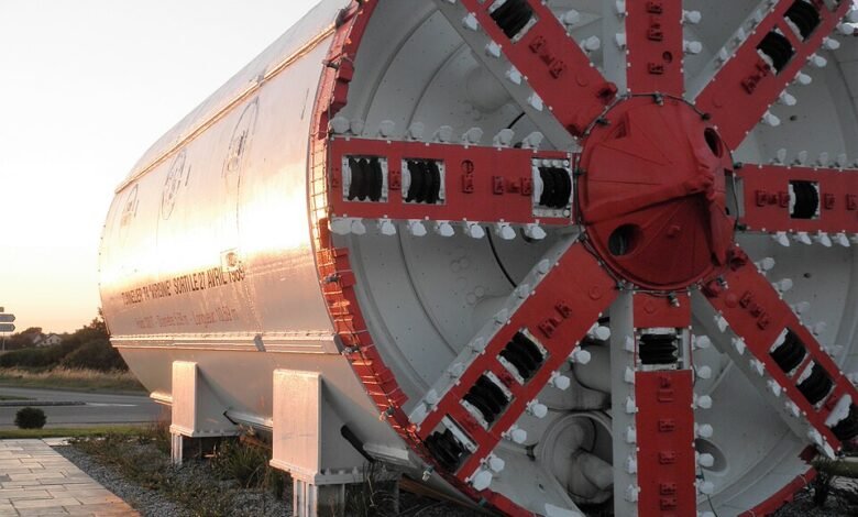
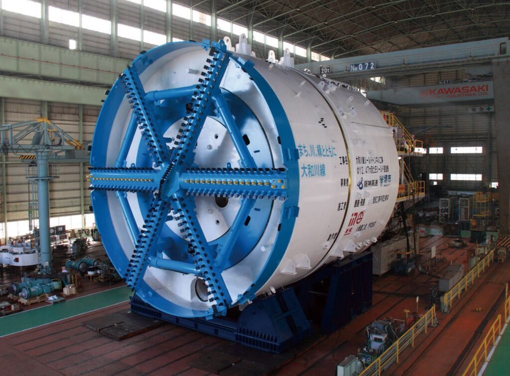
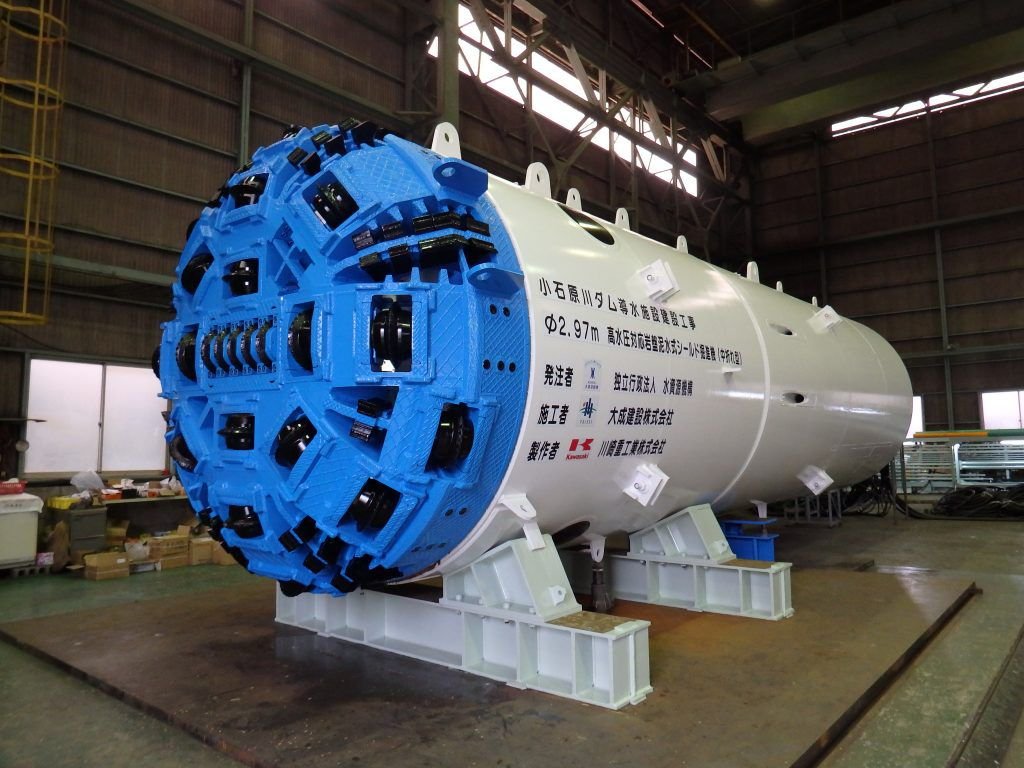
The cutterhead defines a machine’s identity. Hard rock cutterheads carry rows of disc cutters that fracture rock through compressive stress, rolling under thrust until chips shear from the face, while soft ground cutterheads use scraper teeth or carbide bits around openings that let conditioned soil pass into a pressurised chamber. Thrust cylinders push the machine forward by reacting against the most recently installed lining ring, a segment erector positions each precast panel with vacuum pads, and a backup train stretching 100 to 150 metres behind the shield carries the transformers, ventilation, and grout plant that resupply the face.
Types of Tunnel Boring Machines
No single machine handles every ground condition well, which is why manufacturers build distinct configurations around expected geology. The three types of tunnel boring machines explained below, Earth Pressure Balance, slurry shield, and hard rock, cover most drives worldwide, and choosing among them is a geotechnical decision first and a procurement decision second. Getting it wrong shows up the same way poor subgrade characterisation shows up in road construction failures: stalled progress and cost overruns.
1. Earth Pressure Balance Machines
Earth Pressure Balance TBMs excavate soft, cohesive ground using the spoil itself as a pressure-balancing medium. Foam, polymers, or bentonite condition the soil into a semi-plastic paste that fills the excavation chamber and holds back earth and water pressure at the face. EPB machines dominate urban metro construction because they manage face pressures below roughly 7 bar without a separate surface plant, requiring the same discipline around groundwater management as sound surface-level drainage design.
Further Reading: Drainage Design in Road Construction: 5 Proven Fixes for Failure
2. Slurry Shield Machines
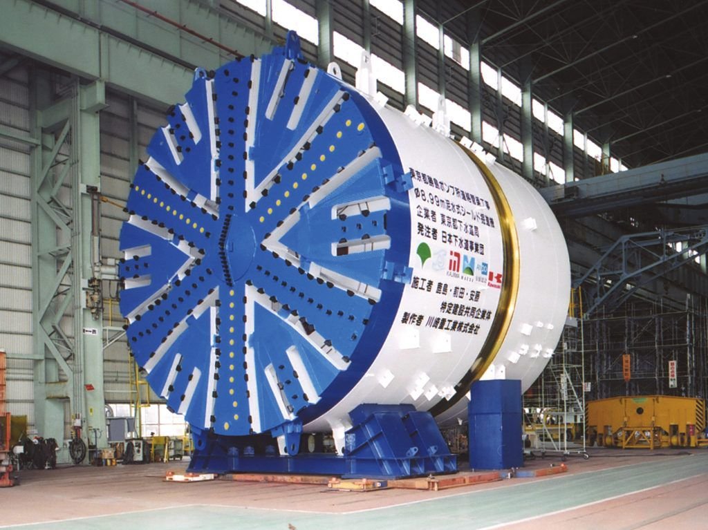
Slurry shield TBMs support the face with pressurised bentonite suspension rather than conditioned spoil, the preferred choice in highly permeable, saturated, or granular ground where an EPB plug cannot hold. Slurry pumps to the cutting chamber, mix with excavated material, and return to the surface for separation before recirculating to the face. This closed loop allows slurry shields to sustain face pressures above 10 bar, well beyond those of an EPB configuration, making them the standard choice for deep river crossings. Cairo Metro Line 2’s crossing beneath the Nile used twin bentonite slurry shield machines roughly 9.4 metres in diameter, one of Africa’s clearest demonstrations of how tunnel boring machines work under sustained hydraulic pressure.
3. Hard Rock TBMs
Hard rock TBMs rely on mechanical fracture rather than pressure management. Disc cutters mounted on the rotating head roll across competent rock, generating stress concentrations that chip fragments away with every pass, while the machine grips the tunnel wall with hydraulic pads to generate the thrust needed to drive the cutters forward. Open main beam machines suit strong, self-supporting rock and use rock bolts, mesh, and shotcrete rather than segmental lining, while single- and double-shield machines add a steel skin for fractured rock. Hard rock configurations account for more than half of the global TBM market, reflecting the extent to which rail, hydropower, and mining infrastructure run through mountainous terrain.
The Tunnelling Process Step by Step
Every TBM tunnelling process follows a broadly consistent sequence regardless of machine type, though pace and required interventions change with ground conditions. This sequence provides a practical overview of how a tunnel boring machine works in the field, from the launch shaft to breakthrough.
Launch Shaft and Assembly
Work begins with a launch shaft, typically 15 to 20 metres in diameter and sunk to the planned tunnel invert. The TBM arrives in sections, since even the largest machines are too large to transport whole. Cranes lower the cutterhead, shield segments, and backup gantries into the shaft for assembly, a process that can take several weeks and demands the same site coordination covered in the site engineer vs. project engineer roles.
Further Reading: Site Engineer vs Project Engineer: 5 Essential Differences Explained
Excavation and Spoil Removal
Once launched, the cutterhead rotates continuously while thrust cylinders push the shield forward at a rate set by penetration per revolution and rotational speed. Spoil moves away from the face through a screw conveyor or slurry pipeline and then through the backup train to the surface, a continuous process with no cycle of drilling, charging, and clearing dust between advances, which is why tunnel excavation methods based on TBMs consistently outpace drill and blast in comparable ground.
Segmental Lining Installation
As the shield advances, a segment erector inside the tail skin lifts precast concrete panels, usually five or six per ring, into a bolted, gasketed ring. Thrust jacks push against this completed ring to drive the machine forward, so lining installation and excavation are mechanically linked rather than sequential. Grout fills the annular gap once a ring clears the tail skin, and on a well-run drive, ring building keeps pace with excavation stroke for stroke, unlike a drill-and-blast heading awaiting temporary support.
TBM Selection Criteria for Ground Conditions
Machine selection starts with a geotechnical baseline, not a manufacturer’s catalogue. Unconfined compressive strength, permeability, groundwater pressure, and the presence of boulders or mixed-face geology all influence whether an EPB, slurry shield, or hard rock configuration will maintain its advance rate. Recent tunnel boring machine technology has directly addressed this uncertainty: an alignment shifting from stable rock to water-bearing sand may justify a multi-mode TBM engineered to convert between EPB and open-face operations with minimal downtime. Urban alignments beneath live infrastructure demand the pressure control EPB and slurry machines provide, since the cost of getting face support wrong under an occupied street far exceeds the premium of a pressurised shield.
TBMs vs Drill and Blast Tunnelling
The TBM vs. drill-and-blast tunnelling comparison comes down to speed, cost, and flexibility, and no single method wins outright. Drill and blast retains an edge in short tunnels and unpredictable geology, since a jumbo rig and blasting crew adapt to a changing profile in ways a TBM cannot. TBMs win decisively on long, consistent-diameter drives, where continuous excavation and simultaneous lining compound into a large schedule advantage.
TBM vs Drill and Blast: Comparative Performance
| Factor | TBM Tunnelling | Drill and Blast |
| Typical advance rate | 200–350 m per month (hard rock) | Approximately 100 m per month |
| Cross-section flexibility | Fixed diameter, set by cutterhead | Adjustable to varying profiles |
| Ground disturbance | Minimal vibration and overbreak | Blast-induced vibration and overbreak |
| Best suited to | Long, consistent-diameter drives | Short or geometrically variable tunnels |
Advance rate benchmarking across Japanese hard rock projects found TBM output running two to three times higher than comparable drill and blast headings, though performance degrades sharply once geology becomes highly variable, precisely where drill and blast retains its advantage.
Applications in Infrastructure Projects
Metro systems remain the largest application for tunnel boring machine technology worldwide, since EPB and slurry shields let cities drive twin-bore alignments beneath dense urban cores with settlement control that cut-and-cover construction cannot match. Hydropower headrace tunnels, water conveyance schemes, and rail corridors through mountainous terrain rely more heavily on hard rock configurations, and matching tunnel excavation methods to the application is as much a strategic decision as an engineering one.
Africa’s tunnelling record, though still limited relative to Asia and Europe, is expanding as metro and water infrastructure programmes mature. Cairo’s metro network has used TBM tunnelling for successive line extensions since the 1990s, and the principles explained above will apply directly to the next generation of projects.
Technical Block: TBM Performance Benchmarks and Engineering Takeaways
Every selection decision covered above eventually comes down to numbers on a programme schedule. The figures below translate the mechanics of cutterhead type, face pressure, and lining sequence into the advance rates that planners actually budget against, followed by the core engineering judgement this article set out to establish.
1. Typical Advance Rates by Machine Type
Advance rate is never a fixed number; it depends on ground conditions, machine diameter, crew experience, and time lost to cutter changes and maintenance. EPB machines in favourable soft ground typically advance 10 to 15 metres per day, while hard rock TBMs under stable conditions advance 200 to 350 metres per month, roughly double the 100-metre benchmark cited for drill-and-blast in comparable rock. Utilisation, the proportion of available time a machine spends cutting rather than waiting on maintenance, often affects overall progress more than raw penetration rate, and studies of major hard rock drives have recorded utilisation below 30 percent on difficult alignments.
Conclusion: Engineering the Underground
Understanding how tunnel boring machines work is no longer a specialist curiosity reserved for tunnelling engineers; it is core knowledge for anyone planning infrastructure that has to cross terrain a road or rail alignment cannot simply grade around. The cutterhead, shield, and segmental lining system work as a single continuous mechanism, and the choice between EPB, slurry shield, and hard rock configurations is determined by geology long before it becomes a procurement conversation.
As African cities pursue metro expansion and as hydropower schemes push further into mountainous terrain, the tunnel boring machine process, step-by-step outlined here, from launch shaft assembly through excavation to final lining, will define how quickly and safely that infrastructure gets built. The judgement that matters most is which configuration matches the ground it will actually meet, and that rests entirely on understanding how tunnel boring machines work before the contract is signed.
Continue Exploring Advanced Tunnel Engineering
Discover more technical tunnel engineering analyses, TBM deep dives, and underground infrastructure reviews on Construction Frontier: Engineering Fundamentals, where complex tunnelling systems and construction methods are explained through practical engineering insight.