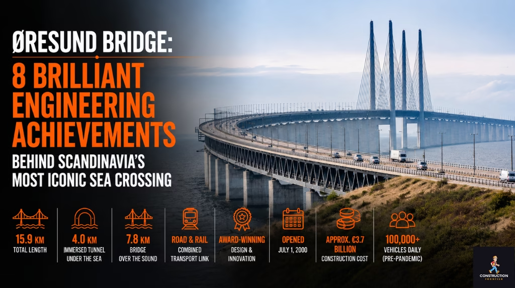
Øresund Bridge: 8 Brilliant Engineering Achievements Behind Scandinavia’s Most Iconic Sea Crossing
The Øresund Bridge is a 16-kilometre combined road and rail link that joins Copenhagen, Denmark, to Malmö, Sweden, across the Øresund Strait. The structure combines a cable-stayed bridge, an artificial island called Peberholm, and the immersed Drogden Tunnel, built between 1995 and 2000 at a cost of roughly DKK 19.6 billion. It remains the longest combined road and rail bridge in Europe and the busiest Denmark-to-Sweden sea crossing on the continent.
Technical Snapshot: Core Project Specifications
| Location | Øresund Strait, between Copenhagen, Denmark, and Malmö, Sweden |
| Total link length | 15.9 kilometres (bridge, island, and tunnel combined) |
| Bridge length | 7.845 kilometres |
| Main span | 491 metres, the longest cable-stayed span carrying both road and rail |
| Tunnel length | 4.05 kilometres (Drogden Tunnel, immersed tube) |
| Artificial island | Peberholm, approximately 4 kilometres long |
| Pylon height | 204 metres |
| Navigation clearance | 57 metres |
| Construction period | 1995 to 2000 |
| Construction cost | Approximately DKK 19.6 billion (around EUR 2.6 billion) |
| Opening date | 1 July 2000 |
| Daily crossings | Roughly 60,000 vehicles and rail passengers combined |
| Ownership | Øresundsbro Konsortiet, jointly held by Denmark and Sweden |
The Øresund Bridge sits at the centre of a project that engineers across Scandinavia still study for its blend of structural ambition and environmental discipline. It connects two capital regions, carries international rail traffic, and demonstrates how a single fixed link can change the economic geography of an entire region.
Introduction: A Fixed Link Decades in the Making
Engineers and planners debated a fixed crossing over the Øresund Strait for most of the twentieth century. The Øresund Bridge tunnel between Denmark and Sweden was not a quick decision. Proposals for a railway tunnel surfaced as early as 1910, a bridge concept followed in 1936, and Danish-Swedish commissions revisited the idea through the 1950s and 1960s without reaching agreement on design or financing. Denmark and Sweden finally signed a binding agreement in 1991 to build the crossing, setting in motion one of the most disciplined infrastructure programmes in Northern Europe.
What makes the Øresund Bridge a genuine case study in engineering judgement is the way the final design balanced three competing constraints: clearance for one of the busiest shipping lanes in Europe, proximity to Copenhagen Airport’s flight paths, and a fixed budget shared between two sovereign governments. Few projects force engineers to resolve maritime, aviation, and political constraints within a single corridor. The result is the Øresund Bridge construction design the region uses today: a bridge, an island, and a tunnel forming a single continuous structure.
This article is one of the supporting pieces in Construction Frontier’s wider analysis of how engineers span open water on the world’s longest sea crossings. It breaks down eight engineering decisions that made the Øresund link possible and explains how the Øresund Bridge’s length, cost, and construction details compare with those of other major fixed links profiled elsewhere on the site. Operational and traffic figures referenced throughout are drawn from Øresundsbro Konsortiet’s own published project data, the joint operator of the link.
How the Øresund Bridge Compares With Other Major Fixed Links
| Project | Total Length | Structure Type | Year Opened |
| Øresund Bridge | 15.9 km | Bridge + island + immersed tunnel | 2000 |
| Hong Kong-Zhuhai-Macau Bridge | 55 km | Bridge + island + immersed tunnel | 2018 |
| Chesapeake Bay Bridge-Tunnel | 28 km | Bridge + trestle + immersed tunnel | 1964 |
| Great Belt Fixed Link | 18 km | Bridge + bored tunnel | 1998 (rail), 1998 (road) |
The Bridge-Tunnel Hybrid That Solved Two Conflicting Constraints
No single structure type could satisfy both the shipping channel and the airport approach path, so the engineering team split the crossing into three connected systems. Understanding how the Øresund Bridge was built between Denmark and Sweden starts with this hybrid logic, because every later design decision flows from it.
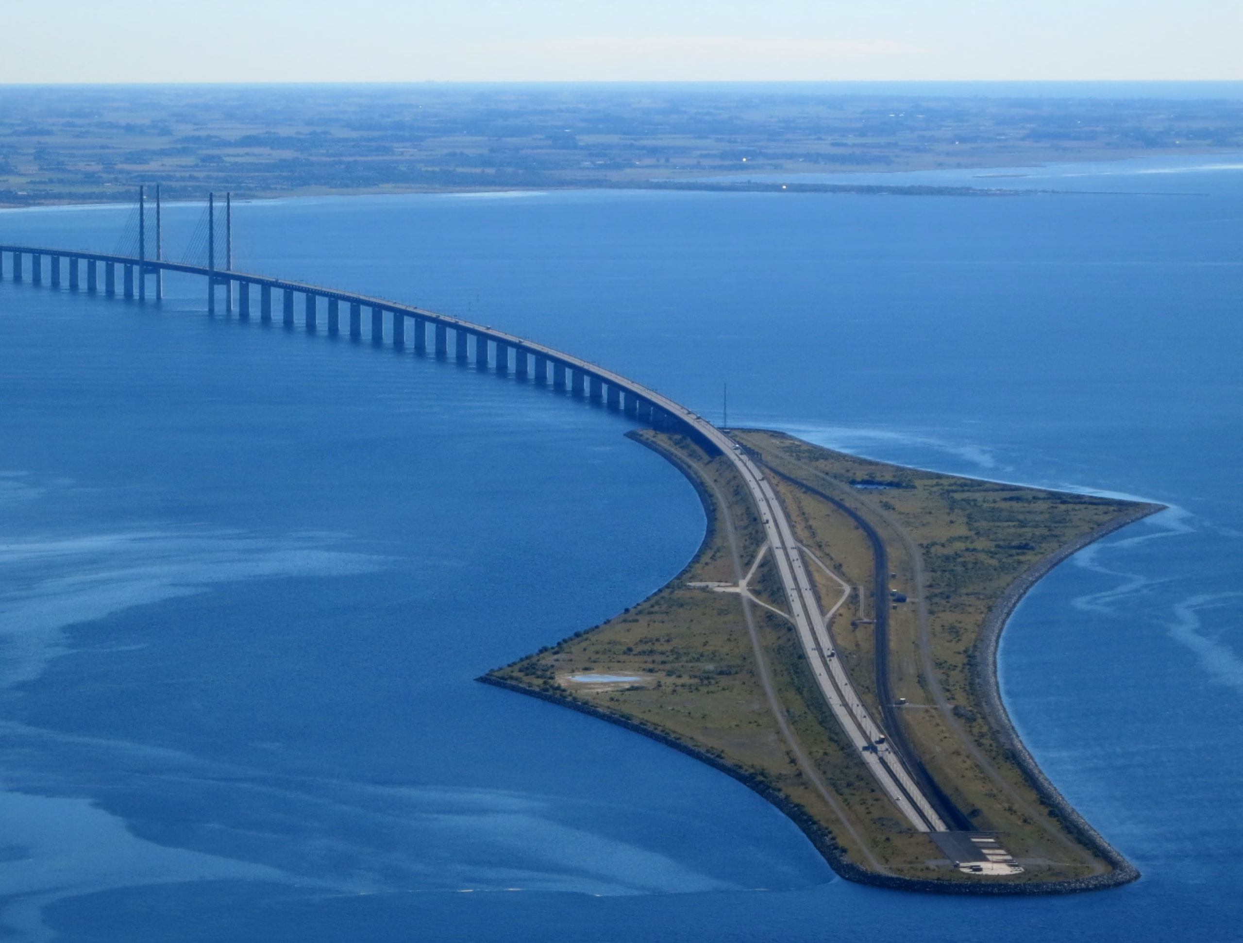
A standard high-level bridge across the entire strait would have intruded on Copenhagen Airport’s glide path on the Danish side. A tunnel across the full distance would have been needlessly expensive given the depth and width of the central channel, where ships need genuine vertical clearance, not a buried route. The design team resolved this by running a cable-stayed bridge across the open, deep-water section near the Swedish coast, dropping into an immersed tunnel on the Danish side closest to the airport, and using an artificial island in between to manage the transition.
That sequencing drives the engineering design of the Øresund Bridge tunnel and the artificial island. Ships need headroom, so the bridge takes the open channel. Aircraft need headroom, so the tunnel takes the section nearest the airport. Neither structure on its own could have satisfied both constraints across the full 16 kilometres.
The Drogden Tunnel and Its Immersed Tube Method
The Drogden Tunnel carries traffic from Peberholm to the Danish island of Amager, and it is the part of the project most directly comparable to other undersea crossings in this cluster, including the Chesapeake Bay Bridge-Tunnel on the American side of the Atlantic.
Constructing a Tube Tunnel on the Seabed
Engineers built the 4.05-kilometre Drogden Tunnel using the immersed-tube method rather than bored tunnelling. Twenty massive concrete elements of 176 metres long, 9 metres high, 40 metres wide, each weighing 55,000 tonnes, were cast in a purpose-built dry dock in Denmark, floated to position using specialised vessels, and then lowered into a pre-dredged trench on the seabed and joined end to end. Once positioned, crews backfilled the trench to lock the segments in place and protect them from shipping anchors and seabed currents.
Keeping the tunnel shallow meant gentler ramp gradients without sacrificing clearance under the navigation channel. Casting the heaviest components on land also gave contractors something underwater concrete pours rarely offer: a chance to inspect every element before it ever touched water, cutting the risk of quality defects on a project this size.
Managing Watertight Joints Under Strait Conditions
Each immersed segment required a watertight connection to its neighbour, despite tidal movement, temperature-driven expansion, and dynamic loading from passing rail traffic. The joints use rubber gaskets compressed by the weight of the segments themselves, a method proven on earlier immersed tube projects but scaled up here to handle both road and double-track rail loads in the same tube. The Øresund Fixed Link engineering team treated joint design as a standalone discipline, running pressure and settlement models separately from the main structural calculations for the bridge spans.
Further Reading: Chesapeake Bay Bridge-Tunnel: 6 Proven Engineering Feats Behind America’s Longest Sea Crossing
Peberholm: Building an Island from Scratch
Peberholm did not exist before construction began. Engineers created it entirely from 6 million m³ of dredged material and 1.6 million tonnes of imported rock to serve as the transition point between the tunnel and the bridge, and its construction reveals as much about environmental engineering as it does about earthworks.
Why an Artificial Island Was Necessary
The original concept proposed two separate bridge spans crossing the strait directly. Detailed hydrographic surveys showed that a single, larger main span over the Flintrännan channel made more structural and navigational sense, but that still left a gap between the tunnel portal and the start of the bridge proper. Rather than build an unnecessarily long approach structure, the design team created Peberholm using soil and rock excavated during tunnel trench and bridge foundation dredging. The island absorbed material that would otherwise have needed disposal, turning a waste-management problem into a structural solution.
Environmental Outcomes Nobody Predicted
Peberholm was deliberately left unplanted so that wind and birds could seed it naturally. Within a few years, it had become one of the richest concentrations of orchid species in Northern Europe and a documented breeding habitat. Planners now point to the island whenever they discuss the long-term ecological impact of the large-scale Denmark-to-Sweden fixed-link bridge-tunnel infrastructure, and it remains a protected nature reserve today.
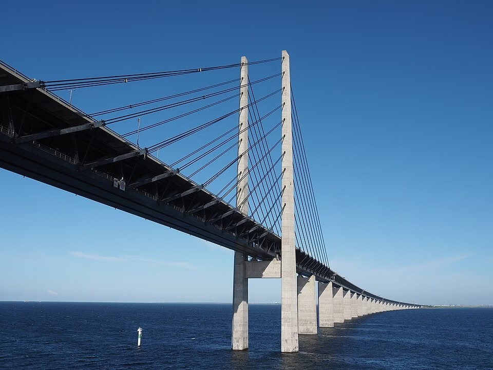
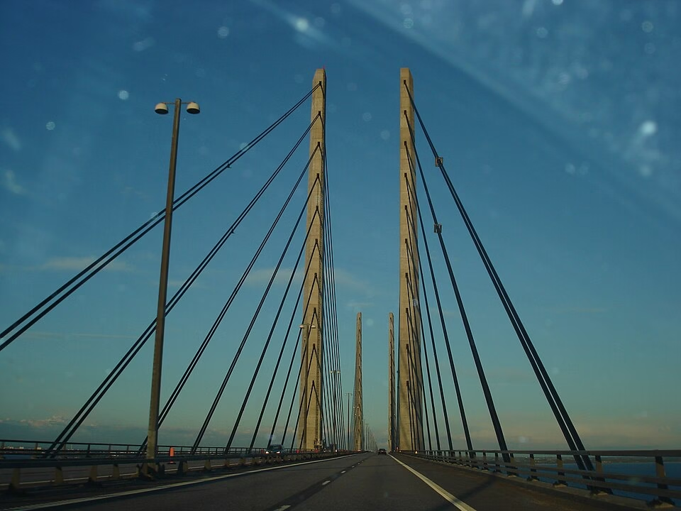
The Cable-Stayed Main Span and Why Suspension Was Rejected
The high bridge section, carrying traffic over the main shipping channel, needed a structural system stiff enough for rail traffic and tall enough for ships, while staying within a tight construction schedule shared by two national contractors.
Why a Suspension Bridge Could Not Carry the Rail Line
A traditional suspension bridge was considered early in the design competition and ruled out. Suspension decks flex more under live load than cable-stayed decks, and that flexibility is incompatible with double-track rail running at speed beneath the road deck. The Øresund Bridge needed a structure rigid enough to keep rail alignment within tight tolerances regardless of wind loading or traffic volume on the upper deck.
The Two-Level Cable-Stayed Solution
The chosen design places four road lanes on the upper deck and two railway tracks on the lower deck, both carried within a single steel-and-concrete girder. Two pairs of pylons, each 204 metres tall, support the 491-metre main span through stay cables anchored along the girder’s full length. Live load runs straight into the towers instead of flexing through the deck, which gives the structure the stiffness rail operations demand. Below it all, ships get 57 metres of clearance, enough for the large container vessels and tankers that pass through the strait daily.
Fabrication and the Role of the Svanen Crane Vessel
Much of what made the construction schedule achievable came down to one piece of equipment and a parallel fabrication strategy that kept work moving on both sides of the strait simultaneously.
Prefabrication at Malmö Harbour
Contractors prefabricated concrete caissons, pier shafts, and railway troughs at a dedicated facility in Malmö’s northern harbour rather than casting them in place over open water. Working under cover meant fewer weather delays and tighter quality control than is typical for marine concrete pours. The two pylon caissons for the high bridge were too heavy even for the project’s main lifting vessel, so crews cast them separately in a dry dock close to the bridge site.
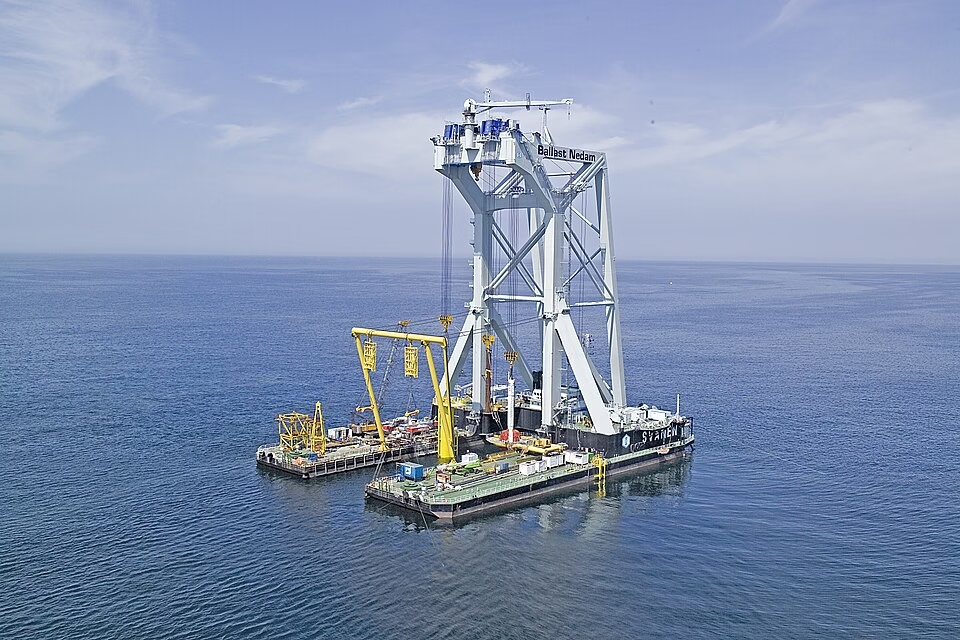
Deploying the World’s Largest Crane Barge
The heavy-lift vessel Svanen, originally built for the Great Belt Fixed Link and later used on Canada’s Confederation Bridge, lifted and placed the prefabricated bridge segments along the Øresund Bridge route. Because it was available, engineers could size the individual precast elements, resulting in fewer lifts, fewer joints, and a faster build. Equipment availability shaping the structural design partway through planning is not unusual; it shows up across major Scandinavian cross-border infrastructure projects of this era.
Resolving Cross-Border Rail and Power Standards
A fixed link between two countries is only useful if trains and signalling systems can actually cross the border without stopping, and Denmark and Sweden operate different electrical and signalling standards.
Switching Electrification Mid-Crossing
Swedish railways operate at 15 kV, 16.7 Hz, while Danish railways operate at 25 kV, 50 Hz. Engineers placed the electrical transition point on the eastern bridgehead at Lernacken, on the Swedish side, so trains switch systems while still moving at controlled approach speed.
Harmonising Signalling Without Slowing Trains
| Parameter | Sweden’s Side | Denmark’s Side |
| Electrification | 15 kV, 16.7 Hz | 25 kV, 50 Hz |
| Signalling system | Swedish ATC, optical signals | Danish ATC |
| Max permitted speed | 200 km/h | Lower, especially in the tunnel section |
| Transition point | Lernacken bridgehead (electrical) | 7 km into Danish territory on Peberholm (signalling) |
Sweden’s ATC signalling system, paired with Swedish optical signals, governs the bridge itself, then hands over to Danish ATC roughly seven kilometres into Danish territory on the western part of Peberholm. Why push the handover that far? Because the Swedish system permits higher speeds, up to 200 kilometres per hour, and costs less to install. Few public accounts of the project mention this kind of cross-system harmonisation, yet it sits among the toughest Øresund Fixed Link construction challenges and specifications the consortium had to work through.
Financing the Øresund Bridge: Two Governments Had to Share Equally
Beyond the structural engineering, the Øresund Bridge required a financing model that two sovereign states could both accept, given that neither wanted to subsidise the other’s side of the link.
A Toll-Funded, Self-Repaying Structure
Denmark and Sweden each hold a fifty percent stake in Øresundsbro Konsortiet, the joint operating company of A/S Øresund (Danish side) and Svensk-Danska Broförbindelsen SVEDAB AB (Swedish side), through their respective national entities. Construction costs, originally around DKK 14.8 billion in 1990 prices, are repaid entirely through bridge tolls and rail usage fees rather than general taxation, with a repayment horizon originally projected at roughly fifty years from the 2000 opening, according to published repayment data from the link’s Danish co-owner. Other Scandinavian cross-border infrastructure proposals have since borrowed the same logic, mainly because splitting the bill evenly removes the political friction of asking one treasury to fund a benefit both nations share.
Splitting Contracts to Manage Risk
The consortium divided the work into separate contracts for the tunnel, the artificial island, and the bridge superstructure, each awarded and managed independently. Specialist contractors could then bid on the scope that matched their expertise, rather than having one firm juggle tunnelling, dredging, and cable-stayed bridge erection under a single contract. The dredging and reclamation methods used on the Hong Kong-Zhuhai-Macau Bridge followed a similar pattern decades later, splitting the work to keep risk from concentrating in any single contractor.
Further Reading: Hong Kong-Zhuhai-Macau Bridge: 10 Brilliant Engineering Feats Behind the World’s Longest Sea Crossing
Technical Block: Maintenance, Data Infrastructure, and What the Project Teaches the Industry
A bridge carrying both rail and motorway traffic across open water cannot rely on conventional inspection methods, so engineers integrated maintenance access directly into the original design of the Øresund Bridge. This closing section also places the project in the wider context of Scandinavian cross-border infrastructure and the lessons it offers future sea-crossing programmes.
1. The Gantry Inspection System
A motorised gantry runs beneath the railway deck for its full length, giving inspection crews direct access to the underside of the structure without lane closures or the mobilisation of marine plant. Daily visual inspections, combined with periodic structural monitoring, feed into a maintenance regime that has kept the bridge operating without major service interruptions since 2000.
2. Data Infrastructure as a Secondary Function
The bridge also carries fibre-optic cable that forms part of the wider European data network, a function rarely mentioned in standard engineering summaries but relevant to anyone assessing the asset’s strategic value. Embedding telecommunications infrastructure within transport infrastructure has since become standard practice on comparable projects, including some of the tunnel works documented in Construction Frontier’s coverage of Europe’s mega tunnel programme.
3. What the Øresund Bridge Teaches the Next Generation of Sea Crossings
The Øresund Bridge engineering facts and technical details matter well beyond Scandinavia because the project proved that a bridge, a tunnel, and an artificial island can function as one integrated system rather than three separate structures bolted together at the edges. Every later Denmark-to-Sweden sea-crossing proposal, and several projects far beyond the region, have borrowed directly from this template.
The lesson that travels furthest is sequencing: solve the navigation constraint with a bridge, solve the aviation constraint with a tunnel, and use an artificial island to absorb the transition cost and the spoil from dredging in one move. That single decision shaped the Øresund Bridge tunnel between Denmark and Sweden into a structure that still functions, twenty-five years after opening, exactly as its designers intended.
Conclusion: Why the Øresund Bridge Remains the Benchmark Fixed Link
The Øresund Bridge stands as proof that two governments, three structural types, and a fixed construction window can still produce an asset that outperforms its original projections for traffic, durability, and ecological outcomes. From the immersed tube sections of the Drogden Tunnel to the cable-stayed main span and the accidental nature reserve at Peberholm, the project rewards close study by anyone working on the next generation of fixed links. The construction programme ran on schedule between 1995 and 2000 despite splitting work across three independent contracts, two national jurisdictions, and two different rail electrification standards, a coordination achievement that gets far less attention than the structural engineering itself but mattered just as much to the project’s success.
What sets the Øresund Bridge apart from many comparable megaprojects is how cleanly its financing model has held up. Tolls and rail usage fees have covered debt service since 2000 without requiring either government to step in with additional subsidy, and the consortium structure that shared ownership and risk equally between Denmark and Sweden has since informed financing discussions for other Scandinavian cross-border infrastructure proposals, including later studies into a fixed link across the Fehmarn Belt. Engineers evaluating future Denmark-to-Sweden fixed-link bridge-tunnel infrastructure, or any comparable crossing elsewhere, will keep returning to the Øresund Bridge as the benchmark for getting a multi-structure sea crossing right on budget, on schedule, and on the first attempt.
Stay Updated on the World’s Most Ambitious Infrastructure Projects
Stay ahead of the engineering decisions shaping the world’s biggest builds with Construction Frontier: Global Mega Projects. Explore deep technical insights, expert analysis, and project intelligence covering the bridges, tunnels, and fixed links redefining how the world crosses open water.