Extreme Environment Bridge Engineering: 4 Proven Global Solutions
Extreme-environment bridge engineering solves problems that standard bridge design was never built to handle: open-ocean currents, active fault lines, canyon depths beyond 500 metres, and ice sheets thick enough to crush a concrete pier. Four completed megaprojects, spanning China, Japan, and Canada, demonstrate the engineering solutions that make these crossings possible.
Technical Snapshot: Four Extreme Environment Solutions
| Extreme Condition | Reference Project | Key Technical Achievement |
| Open ocean crossing | Hong Kong-Zhuhai-Macao Bridge, Pearl River Estuary | Twin 100,000 m² artificial islands formed in roughly 220 days using deep-inserted steel cylinders |
| Active seismic zone | Akashi Kaikyo Bridge, Akashi Strait, Japan | The dual-hinged girder system, rated for magnitude 8.5, survived the 1995 Kobe earthquake mid-construction |
| Deep valley span | Beipanjiang (Duge) Bridge, Guizhou Province | The deck, suspended 565 metres above the gorge floor, erected using cable cranes and incremental launching |
| Extreme cold and ice loading | Confederation Bridge, Northumberland Strait | Forty-four conical gravity piers engineered to fracture sea ice in flexure rather than absorb full impact force |
Each of these four cases pushed a different discipline within extreme-environment bridge engineering to its limits, and each produced a repeatable engineering method that now guides megaprojects on every continent.
Introduction: Extreme Environment Bridge Engineering
Most bridges are built over predictable ground, moderate currents, and manageable spans. Extreme-environment bridge engineering exists for sites that fail that description: deep-ocean channels, tectonically active straits, and gorges where a conventional pier simply cannot reach the ground. Height and span records, with these 10 record-breaking tallest bridge designs among them, are rarely achieved by scaling up an existing design. They are achieved by solving a specific site problem that has never been solved at that scale before.
This article examines four of those problems in detail: crossing open ocean, surviving a major earthquake, spanning a canyon deeper than most skyscrapers are tall, and founding piers in ice-choked waters. Each case study draws on a completed operating structure with a verified engineering record, rather than a theoretical design exercise. Together, they form a practical reference for engineers, investors, and project planners assessing bridge crossings in genuinely difficult terrain.
Bridge Construction Over Oceans: Offshore Engineering at Scale
Bridge construction over oceans introduces a category of problem that inland engineering rarely encounters: constructing permanent, load-bearing structures in open water subject to tides, strong currents, and dense shipping traffic, all while limiting environmental disruption to a live marine ecosystem. Offshore bridge engineering on this scale requires floating plant, prefabricated components, and foundation systems that can be installed without ever draining the working area.
Building Artificial Islands in Open Water
The Hong Kong-Zhuhai-Macao Bridge answers the question of how engineers build bridges over oceans when a fixed link needs to cross more than 55 kilometres of the Pearl River Estuary while still allowing large vessels through the shipping lanes. Rather than running a bridge deck across the entire crossing, engineers combined 22.9 kilometres of cross-sea bridge with a 6.7-kilometre immersed tunnel, connected by two artificial islands that act as transition points between the two systems.
Each island covers around 100,000 square metres and sits on soft estuarial ground roughly 30 metres thick. The original construction method would have taken years to build a stable platform on that seabed. Instead, engineers used 120 deeply inserted steel cylinders, every 22 metres in diameter and up to 50 metres tall, to form the enclosing walls of both islands. The two islands were completed in 207 days, a rate the project team described as the fastest construction of offshore artificial islands achieved in China at that time. This single decision reshaped the schedule for the entire link and remains one of the clearest demonstrations of offshore bridge engineering solving a foundation problem through island construction rather than conventional piling.
Offshore Bridge Foundations Under Tidal and Current Loading
Offshore bridge foundation engineering on the Hong Kong–Zhuhai–Macao Bridge project extended well beyond the artificial islands. The immersed tunnel connecting the islands reaches 48 metres beneath the South China Sea at its deepest point and is built from 33 precast tunnel elements, each measuring 180 metres long, 38 metres wide, 11.4 metres high, and weighing roughly 80,000 tonnes. Every element was cast on Guishan Island near Zhuhai and towed to the site by tugboat before being lowered into position.
The main bridge sections again needed a different foundation solution. The Hong Kong-Zhuhai-Macao Bridge’s cable-stayed spans cross the primary shipping channels, a configuration chosen to provide vessels with the clearance they need. Combining artificial islands, an immersed tunnel, and cable-stayed spans within one 55-kilometre corridor illustrates why bridge construction over oceans rarely relies on a single structural system. Every extreme-environment bridge engineering solution on this scale is really a portfolio of solutions, matched to the specific stretch of water it crosses.
Bridge Engineering in Seismic Zones: Designing for Active Fault Lines
Bridge engineering in seismic zones has to account for ground motion that can shift a structure’s geometry before construction even finishes. The Akashi Kaikyo Bridge in Japan remains the definitive case study, not because it was designed in theory to withstand a major earthquake, but because it was tested by one while its towers were already standing.
Earthquake-Resistant Bridge Design Principles at Akashi Kaikyo
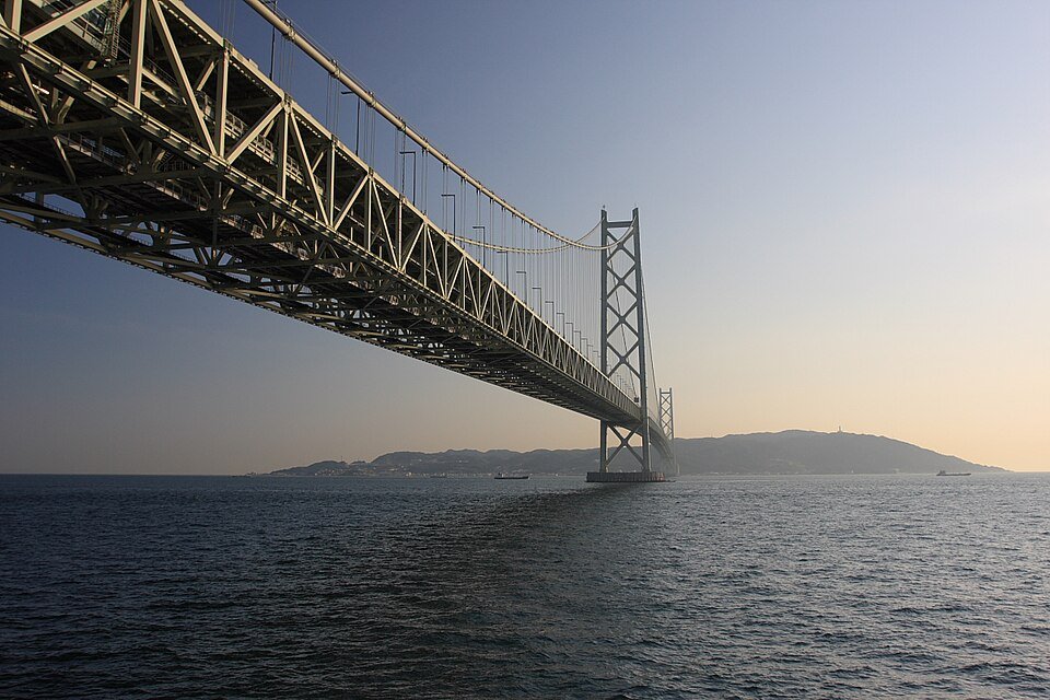
The Akashi Kaikyo Bridge crosses the Akashi Strait between Kobe and Awaji Island with a main span that was, at completion, the longest central span of any suspension bridge in the world. The bridge was designed with a dual-hinged stiffening girder system, allowing the structure to withstand winds of 286 kilometres per hour and earthquakes measuring up to magnitude 8.5. This design choice sits at the centre of the bridge’s earthquake-resistant principles: a hinged girder can flex and redistribute seismic loads rather than transfer the full force directly to the towers.
The towers also contain tuned mass dampers designed to reduce vibration during both earthquakes and typhoons. For readers who want to understand suspension bridge structures, our article on suspension bridge engineering design explains why this configuration was chosen over a stiffer alternative. Foundation construction itself relied on a laying-down caisson method to establish deep foundations in fast tidal currents, a technique developed specifically for this project.
Further Reading: Suspension Bridge Design: 5 Proven Principles for Structural Stability
When the Kobe Earthquake Tested the Bridge Mid-Construction
Bridge construction in seismic zones explained through theory is one thing. The Akashi Kaikyo project tested its design against a real event before the deck was even built. On 17 January 1995, the Great Hanshin earthquake, with an epicentre roughly 20 kilometres west of Kobe, struck while both towers were standing and the main cables were under construction. The event moved the towers apart, requiring the planned 1,990-metre central span to be extended by one metre to 1,991 metres.
Engineers confirmed the earthquake caused displacement at four foundations but produced no structural damage to the bridge itself. Detailed post-earthquake surveys found the foundations had moved together with the surrounding ground rather than sliding against it, which limited the practical impact of the shift. Because the roadway deck had not yet been installed, the correction was absorbed by adjusting truss member lengths rather than triggering a full redesign. This single event remains one of the strongest real-world validations in earthquake-resistant bridge design, and it explains why the Akashi Kaikyo case is still referenced in seismic bridge engineering standards worldwide.
Akashi Kaikyo Bridge: Seismic and Wind Design Parameters
| Design Parameter | Specification |
| Design wind resistance | 286 km/h |
| Design earthquake magnitude | Up to 8.5 |
| Tower height above sea level | 282.8 metres |
| Central span (post-1995 adjustment) | 1,991 metres |
| Earthquake damage recorded (1995 Kobe event) | None to the superstructure; displacement recorded at four foundations |
Deep Valley Bridge Construction: Engineering Above the Void
Deep-valley bridge construction eliminates the option of building from the ground up in the conventional sense. When the intended crossing sits hundreds of metres above a gorge floor, there is no scaffolding solution and no straightforward access route for materials or labour. The Beipanjiang Bridge, widely known as the Duge Bridge, in Guizhou Province, is one of the clearest illustrations of how this problem gets solved.
Cable Crane Erection Over the Beipan River Gorge
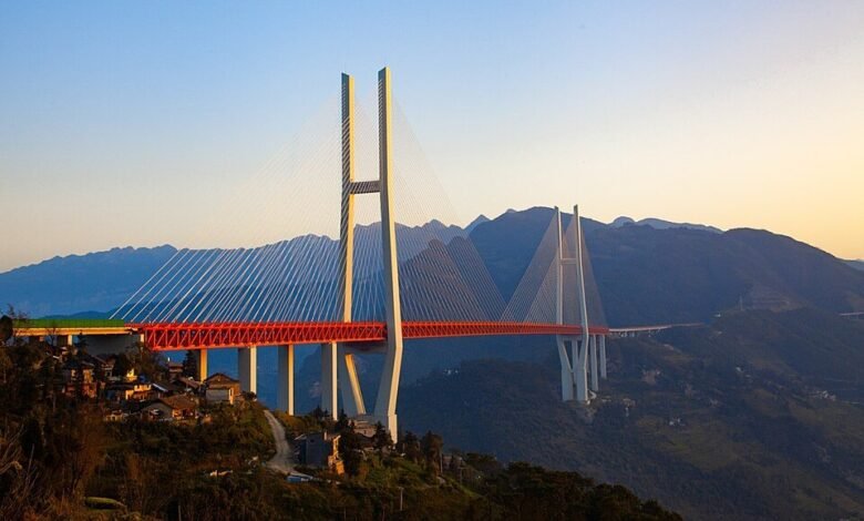
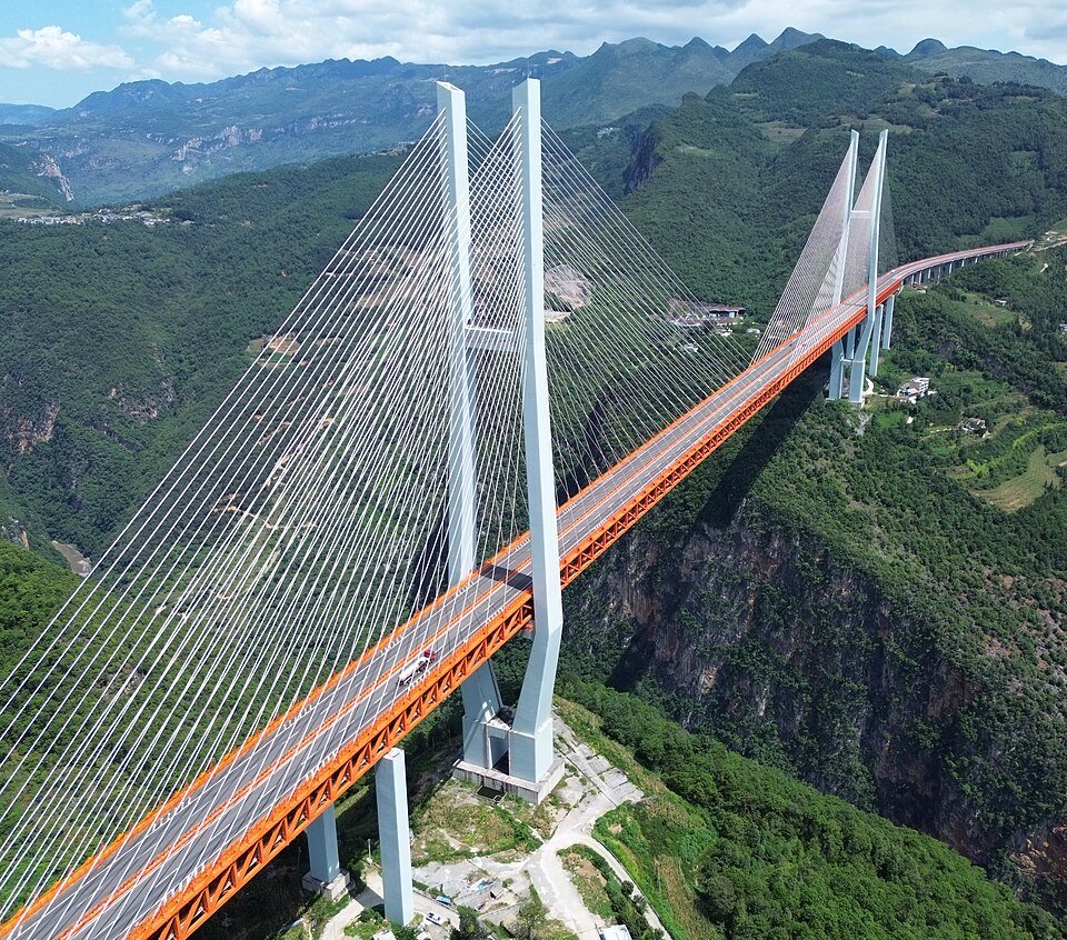
The Duge Bridge is a four-lane cable-stayed bridge on the border between Guizhou and Yunnan provinces, spanning the gorge of the Nizhu River, a tributary of the Beipan. Its road deck sits over 565 metres above the floor of the gorge, a height that made it the world’s highest cable-stayed bridge from 2016 until 2025. Deep valley bridge engineering challenges of this scale rule out conventional erection methods entirely, since no crane or falsework can operate safely at that height above a canyon floor.
The Duge Bridge design shows how the project team used drones and cable trolleys to string pilot lines across the canyon before hanging the main cables that would carry the steel truss deck. Steel deck sections were prefabricated off-site and lifted into position using synchronised winches, with engineers applying incremental launching to slide deck segments across the suspended cables until both sides connected.
Load Testing and Precision at Extreme Height
Once assembly was finished, the bridge underwent dynamic load testing simulating wind, traffic, and seismic conditions, with a final deflection of less than 15 centimetres over a span of more than a kilometre. That level of precision, achieved on a structure hanging 565 metres above a river, sets the benchmark that subsequent deep-valley bridge construction projects have had to match or surpass.
The record did not stand indefinitely. The Huajiang Canyon Bridge, also in Guizhou, later surpassed it with a deck 625 metres above the water, employing an intelligent cable crane system and high-strength alloy-coated cables, built directly on lessons learned from the Duge project. The wind loading that comes with building at this altitude above a canyon is a discipline that both the bridge aerodynamics and wind load engineering teams had to design against. Between Duge and Huajiang, Guizhou Province now hosts a working demonstration of how deep-valley bridge construction methods compound and improve within a single decade.
Deep Valley Span Comparison: Duge and Huajiang Canyon Bridges
| Bridge | Deck Height Above Ground | Structural System |
| Beipanjiang (Duge) Bridge | 565 metres | Cable-stayed, H-shaped concrete pylons |
| Huajiang Canyon Bridge | 625 metres | Suspension, intelligent cable crane erection |
Further Reading: Bridge Aerodynamics: 5 Powerful Solutions That Prevent Collapse
Bridge Foundations in Extreme Conditions: Engineering for Ice and Cold
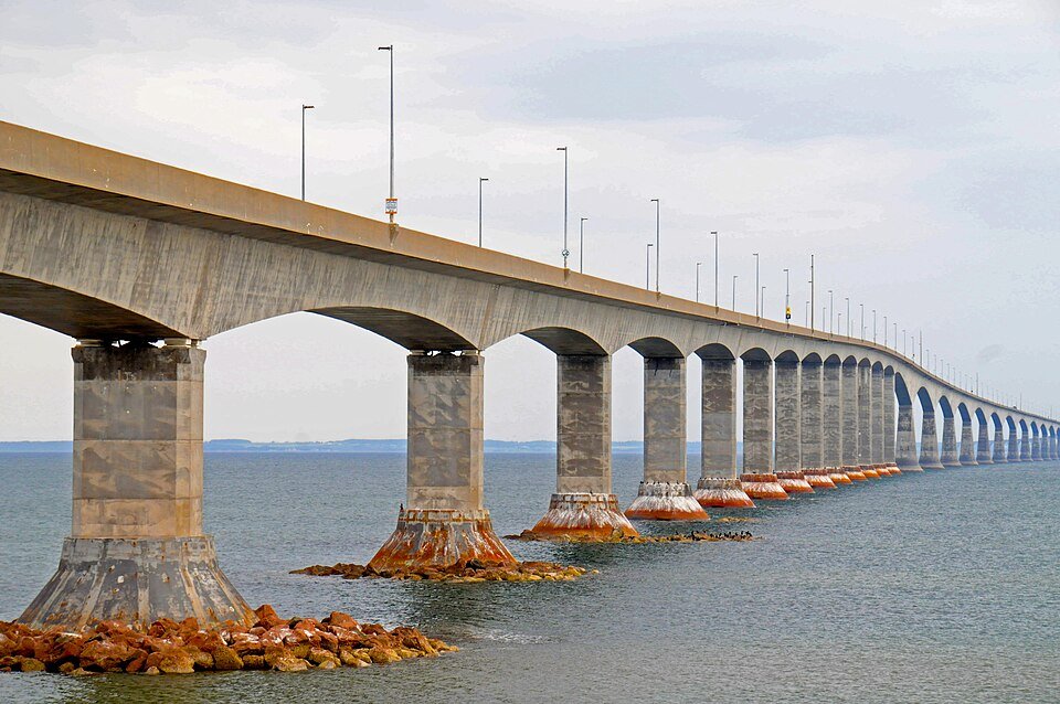
Bridge foundations in extreme conditions face a different kind of load entirely once the water they sit in freezes for part of the year. The Confederation Bridge, connecting Prince Edward Island to New Brunswick across the Northumberland Strait, was built specifically to survive seasonal sea ice without the pier damage that ice sheets typically inflict on marine structures.
Conical Piers That Defeat Ice Rather Than Resist It
The 12.9-kilometre Confederation Bridge crosses 11 kilometres of open strait using 44 main piers plus 16 approach piers, spaced at intervals of up to 250 metres to limit the number of obstructions ice floes would encounter. Extreme-weather bridge construction techniques on this project centred on a single design detail: the shape of the pier at the waterline.
Each pier features a conical ice shield, sloped at 52 degrees, engineered to fracture ice in flexure within the tidal zone and to force ice upward rather than let it strike the pier directly. The shields themselves were built from high-performance concrete rated up to 100 MPa, tough enough to survive continuous ice abrasion. This approach converts a load the pier would otherwise have to absorb into a failure mechanism that the ice itself initiates on contact, a distinction that separates genuinely extreme-environment bridge engineering from simply overbuilding a standard pier.
Foundation Design in a Narrow Construction Window
Engineers on the project faced deep water, high lateral and eccentric loads, complex geology, and a construction window shortened every year by ice and severe weather. Because the seabed consisted of irregular, weathered mudstone unsuited to conventional levelling, each 4,000-tonne precast pier base was set onto grouted hard pads: fabric formwork bags filled with cement grout that expanded to match the seabed’s exact profile before the pier was lowered into place.
Two decades of ice load monitoring have since confirmed the design’s margins. The highest ice load ever measured on a single pier across twenty years of monitoring reached just over 8 meganewtons, comfortably within the range analysts had projected before construction began. That monitoring record is what makes the Confederation Bridge a genuine reference point for bridge foundations in extreme conditions rather than a one-off solution: the data confirms the design assumptions held up under real winters, not just wind-tunnel and laboratory models.
The underlying logic of how piers, girders, and deck systems share load rules out a suspended or cable-supported system here, making the right foundation choice for this ice-facing site. Understanding how these structural forms distribute loads is fundamental to bridge engineering, as explained in our design techniques for beam, arch, and truss bridges.
Confederation Bridge: Ice-Resistant Pier Design Data
| Design Feature | Specification |
| Number of main piers | 44, spaced up to 250 metres apart |
| Ice shield cone angle | 52 degrees |
| Ice shield concrete strength | Up to 100 MPa (high-performance concrete) |
| Maximum recorded single-pier ice load (20-year record) | Just over 8 MN |
| Design service life | 100 years |
Technical Block: Standards Across Extreme Environment Bridge Engineering
Extreme-environment bridge engineering draws on a small set of recurring principles regardless of the specific hazard a project addresses. This technical block consolidates the shared standards visible across all four case studies, from ocean crossings to ice-bound straits, before closing with the practical takeaways for teams assessing similar sites.
1. Site-Specific Load Cases Drive the Foundation Method
None of the four projects covered here used a generic foundation solution. The Hong Kong-Zhuhai-Macao Bridge team chose steel cylinder islands because the estuarial seabed could not support conventional piling within the construction schedule. The Confederation Bridge team chose conical gravity piers because sliding ice, rather than vertical loads, was the dominant design case. Deep-valley bridge engineering challenges at Duge ruled out ground-based erection entirely, necessitating a cable crane solution. In every case, the extreme condition itself, not a standard code minimum, determined the foundation and erection method.
2. Monitoring Extends the Design Life of Extreme Structures
The Confederation Bridge and Akashi Kaikyo Bridge both rely on long-term instrumentation, tiltmeters and ice load sensors on the former and seismic response records on the latter to confirm that as-built performance matches design assumptions. This continuous verification is what allows engineers to certify a 100-year service life on structures operating well outside typical design margins.
Conclusion: What Extreme Environment Bridge Engineering Proves
These four projects show that extreme environment bridge engineering is not a single discipline but a set of transferable methods matched precisely to a hazard: artificial islands and immersed tunnels for open ocean crossings, hinged girders and tuned mass dampers for active fault zones, cable crane erection for canyons too deep to scaffold, and conical piers for ice-laden straits. None of these solutions was theoretical. Each was tested by the exact condition it was designed for, most dramatically at Akashi Kaikyo, where a magnitude 7.3 earthquake struck the site mid-construction and the design held.
For engineers and investors assessing a crossing in difficult terrain, the lesson from all four sites is consistent. The extreme condition should be identified and quantified first, whether that is tidal current, seismic magnitude, canyon depth, or ice thickness, and the foundation and erection method should be selected to answer that specific condition rather than be adapted from a standard design. That sequencing, hazard first and structure second, is what separates a bridge that survives its environment from one that merely tolerates it until the next major event.
Explore More of Mega Bridge Engineering
Extreme-environment bridges showcase how engineers overcome the world’s toughest site conditions. Explore Construction Frontier: Engineering Fundamentals for expert technical analysis, engineering deep dives, and project reviews covering long-span bridges, structural innovation, and record-breaking bridge megaprojects.