Soil Investigation for Civil Works: 7 Essential Steps for Safe Urban Foundations
Soil investigation for civil works is a structured process for assessing ground conditions before a structure is designed, combining desk studies, field drilling, in situ testing, laboratory analysis, and groundwater assessment. In dense cities, this process runs through seven essential steps that determine whether a foundation performs safely across a fifty-year design life or fails within a decade. Engineers who skip or compress these steps inherit risks that surface only after the concrete has cured.
Technical Snapshot: Soil Investigation for Civil Works
| Parameter | Typical Value/Practice |
| Standard borehole spacing (urban sites) | 25–50 m grid, or one per structure footprint |
| Minimum investigation depth (low-rise) | 1.5 times the foundation width below the founding level |
| Minimum investigation depth (high-rise/piled) | Depth of significant stress influence, often 20–40 m |
| SPT test interval | Every 1.5 m or at a material change (ASTM D1586) |
| CPT push rate | 20 mm/s ± 5 mm/s (ASTM D5778) |
| Governing standards | BS EN 1997-2 (Eurocode 7), ASTM D1586, ASTM D5778, BS 5930 |
| Typical urban SI duration | 2–6 weeks, site-access dependent |
A properly scoped soil investigation for civil works is the single cheapest insurance policy on any urban project, typically costing under 1% of construction value while preventing failures that can cost 10 to 50 times as much to remediate. No amount of site investigation or civil engineering budget cut ever pays for itself once a foundation is already in the ground.
Introduction: Soil Investigation in Urban Civil Works
Every structure eventually meets the ground, and the ground rarely behaves the way a drawing assumes it will. Soil investigation for civil works exists to close that gap between assumption and reality before the first pile is driven or the first footing is poured. It is the discipline that tells an engineer whether a site sits on stiff clay or loose fill, whether the water table will fight the excavation, and whether a raft foundation will settle evenly or tilt a building over twenty years.
In cities, this work carries more weight than it does on open land. A road cannot be widened, a metro station cannot be sunk, and a tower cannot rise without first answering the same question a bridge deck or an embankment asks earlier in its own life: what is actually underneath us? That question sits at the foundation stage of the broader road construction lifecycle, where subgrade and formation decisions made during geotechnical investigation ripple through every subsequent stage, from earthworks to pavement design. Get the soil investigation for civil works wrong at this early point, and every downstream stage inherits the error.
This guide walks through the geotechnical and soil investigations for civil works that urban engineers actually run, from the desk study that sets the scope to the laboratory tests that produce design parameters. It sets out urban soil testing methods that account for buried services, contaminated ground, and restricted access, and it closes with the standards and depth guidelines that turn field data into a foundation an owner can build on with confidence. Anyone asking how to conduct a soil investigation in cities is really asking how to sequence these seven steps correctly under conditions a rural or greenfield programme never has to face.
Why Urban Soil Investigation Differs from Greenfield Sites
A soil investigation for civil works varies depending on where it is conducted. A greenfield site gives an engineer room to work: open access for drilling rigs, undisturbed natural ground, and few surprises beyond the geology itself. An urban site doesn’t give any of that for free. The soil investigation process in a city has to account for decades, sometimes centuries, of prior construction, demolition, and dumping, layered beneath streets that are themselves full of live infrastructure. Two factors dominate this difference and shape almost every decision that follows in the investigation programme. Any geotechnical site investigation an urban construction team runs will spend more time managing these two factors than it spends interpreting the geology itself.
Site Access and Utility Constraints
Drilling rigs are large, and city plots are small. A standard truck-mounted rotary rig needs a working platform of several metres in every direction, headroom clear of overhead cables, and a route in that does not cross a live carriageway. Few urban infill sites offer all three. Engineers planning a site investigation civil engineering programme in a built-up area routinely trade a full-size rig for a smaller tracked or man-portable percussion rig, accepting slower progress in exchange for the ability to work inside a basement, a car park, or a narrow gap between existing buildings. This trade-off is one of the clearest markers separating urban soil testing methods from their rural equivalents.
Utility congestion compounds the access problem in any soil investigation for civil works run inside a live city grid. A typical city street carries water mains, gas lines, power cables, fibre ducts, and stormwater or foul sewers, often documented only to modern standards. Before any borehole is sunk, the investigation team must confirm the position with utility surveys, ground-penetrating radar, and hand-dug inspection pits, because a single strike on a live gas main can turn a routine soil investigation for civil works into an emergency.
Contaminated and Made Ground
Urban plots are rarely virgin ground. Many sit on fill placed decades ago to level a site, bury demolition rubble, or reclaim land from a floodplain. This made the ground behave nothing like natural soil: its density is inconsistent, its composition unpredictable, and its bearing capacity is often too low to trust without significant improvement or piling. A soil investigation process that treats made ground as ordinary fill risks handing the structural engineer parameters that overstate strength and understate settlement.
Contamination adds a second layer of risk. Former industrial land, filling stations, tanneries, and informal dump sites leave chemical residues that affect both construction safety and long-term durability, attacking buried concrete and steel or posing a hazard to site workers during excavation. Recognising this risk early, during the desk study rather than after excavation has started, keeps the programme on schedule and keeps site staff safe. This is precisely why soil testing methods for urban construction projects always pair a chemical screen with the physical strength testing that classic soil investigation for civil works has traditionally focused on.
Desk Study and Preliminary Site Assessment
Before a single borehole is drilled, an experienced geotechnical team builds a picture of the site from existing records. This desk study stage is where the bulk of the investigation’s cost efficiency is decided: a thorough review can cut the number of exploratory boreholes needed by identifying where risk actually concentrates, while a rushed one leaves the field team drilling blind. The steps in soil investigation for civil engineering works always begin here, on paper and in the archive, long before the rig arrives.
Historical Land Use Review
Old maps, aerial photographs, and municipal planning archives tell a story that the surface of a modern plot completely hides, and correctly reading that story is one of the earliest steps a team can take in soil investigation for civil engineering works. A site that looks like flat, unremarkable ground today might have been a quarry, a landfill, a railway marshalling yard, or a wartime bomb site a century ago. A historical land use review pulls together sequential map editions; satellite and aerial imagery, where available; and any planning or demolition permits on file, building a land use timeline that flags where made ground, contamination, or buried structures are most likely to appear.
This review also catches obstructions that would otherwise stop a drilling crew cold: old building foundations, mineshafts, culverts, and disused wells that do not appear on any current utility plan. Coordinating this desk research with the roles a site engineer typically manages on site ensures the findings translate directly into a drilling plan the field crew can actually execute, rather than staying trapped in a report nobody reads before mobilisation.
Existing Borehole and Geological Data
Few urban sites are investigated in true isolation. National geological surveys, municipal infrastructure archives, and neighbouring project files often already hold borehole logs, geological maps, and groundwater records covering the same ground or ground close enough to be useful. Pulling these records is one of the fastest ways to shorten a soil investigation process, because they let the geotechnical engineer plan borehole positions and depths around known strata rather than guessing.
Regional geological memoirs and published soil maps add broader context: whether the area sits on alluvial deposits prone to soft compressible clay, on residual tropical soils with unpredictable weathering profiles, or on rock close enough to the surface to change the foundation strategy entirely. None of this data replaces new fieldwork, but it sharpens the focus of that fieldwork and provides the eventual geotechnical report with a regional baseline to compare against. This is often the fastest practical way to conduct a soil investigation in cities where archive records are patchy but not entirely absent, and it is a step every geotechnical site investigation urban construction team should complete before mobilising a rig.
Field Investigation Methods
A desk study sets the plan; a field investigation tests it against reality. This stage puts people, rigs, and instruments on the ground to recover samples and record in situ measurements that no archive can substitute for. Urban soil testing methods at this stage are split into four main techniques, each suited to a different combination of ground conditions, structure type, and site constraints. Where a project moves below the surface entirely, such as a metro alignment or utility tunnel, the same field methods extend into a deeper, continuous ground model, the same subsurface picture that determines how a tunnel boring machine advances safely through mixed strata without stalling on an unexpected boulder or void.
Further Reading: How Tunnel Boring Machines Work: 5 Powerful Stages of Tunnelling
Field Investigation Method Comparison
| Method | Typical Depth Range | Primary Output | Best Suited For | Urban Access Demand |
| Borehole (rotary/percussion) | Unlimited, typically 6–40 m | Disturbed and undisturbed soil samples | Piled foundations, deep excavations | High: full or tracked rig footprint |
| Standard Penetration Test | Within the borehole, every 1.5 m | N-value and disturbed sample | Bearing capacity, relative density | High: run inside a borehole |
| Cone Penetration Test | Typically 20–30 m | Continuous tip and sleeve resistance profile | Stratigraphy, soft layer detection | Moderate to high: reaction frame required |
| Trial Pit | 3–4 m | Visual soil profile and shallow samples | Shallow foundations, obstruction checks | Low: hand or mini-excavator access |
Borehole Drilling and Sampling
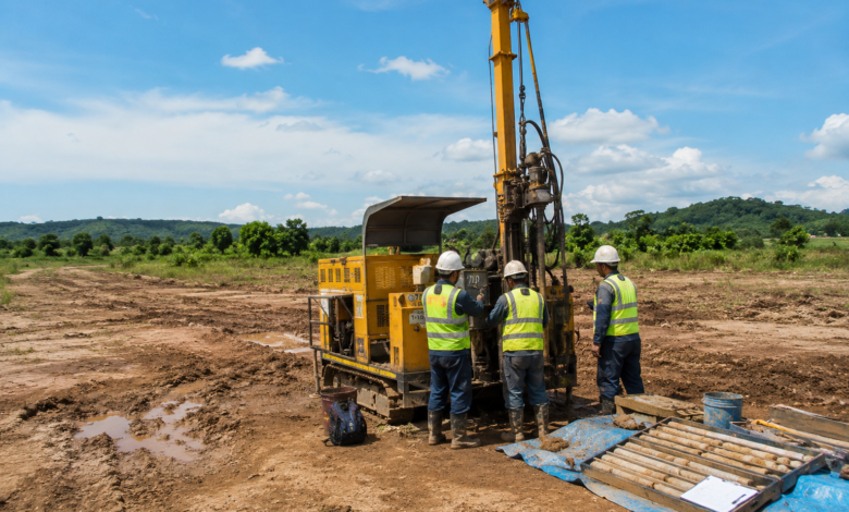
Boreholes remain the backbone of any soil investigation for civil works because they are the only method that recovers physical soil for direct examination and laboratory testing, and they anchor almost every geotechnical investigation urban engineers commission, regardless of which supplementary field tests are run alongside them. Rotary drilling, cable percussion, and hollow-stem auger rigs each suit different ground: rotary methods cut efficiently through mixed strata and rock, cable percussion suits softer soils and shallow urban work where access is tight, and hollow-stem augers allow sampling without drilling fluid, useful where contamination cross-flow is a concern.
Sampling within the borehole follows a disturbed-versus-undisturbed logic. Disturbed samples recovered by auger cuttings or split-spoon samplers are sufficient for classification tests such as moisture content and grading. Undisturbed samples, typically taken with thin-walled tube samplers pushed rather than driven into cohesive soil, preserve the soil’s natural structure and are essential for strength and consolidation testing. Getting this split right at the point of sampling avoids the common and costly mistake of running a shear strength test on a sample too disturbed to give a meaningful result. It is also one of the most frequently overlooked steps in soil investigation for civil engineering works, as a poorly logged sample undermines every subsequent laboratory result.
Standard Penetration Testing
The Standard Penetration Test is the most widely used in-situ test in geotechnical practice, and for good reason: it produces both a disturbed sample and a direct measure of soil resistance in a single operation. Under the governing test method, a split-barrel sampler is driven into the base of a borehole by a 63.5 kg hammer dropped from a standard height of 750 millimetres, with the blow count recorded over three successive 150 mm increments. The sum of blows over the final two increments gives the N-value, the number engineers correlate against relative density in sands and undrained shear strength in clays.
Because the test is simple, reliable, and cheap relative to the data it returns, it is run at close, regular intervals through a borehole, typically every 1.5 m or wherever the drilling crew logs a change in material, and the results form the spine of most bearing capacity calculations used in the soil investigation process for shallow and piled foundations alike. Very few urban soil testing methods deliver as much design value per unit cost as this one test, run consistently and logged correctly.
Cone Penetration Testing
Where ground conditions allow, cone penetration testing offers a faster, more continuous alternative or complement to boreholes. A cone-tipped probe is pushed into the ground at a steady rate, and the resistance at the tip and along a friction sleeve is logged electronically in a near-continuous profile rather than at discrete intervals. Modern piezocone variants include a pore pressure sensor, turning the test into a tool for measuring groundwater conditions and soil stratigraphy in a single push.
This continuity is the method’s real advantage over boreholes: a cone penetration test can flag a thin soft layer, a buried void, or a firm stratum boundary that a 1.5 m sampling interval in a borehole might miss entirely. Its main limitation in dense cities is access, since the reaction frame needed to push the cone requires either a heavy rig or an anchored platform, both harder to mobilise on a constrained infill plot than a lighter percussion rig. Where access allows, it remains one of the fastest urban soil testing methods available for building a continuous stratigraphic profile.
Trial Pits in Constrained Sites
Not every urban site can accommodate drilling, and not every site investigation civil engineering programme needs to go deep. Trial pits, excavated by hand or with a small mechanical excavator, expose the near-surface soil profile for direct visual logging, in situ density testing, and shallow sampling, usually to depths of 3 to 4 m before instability or groundwater makes deeper excavation unsafe without shoring. For shallow strip and pad foundations, retaining wall checks, and pavement subgrade assessment, a trial pit often gives more usable information per hour on site than a borehole, because the engineer can see and log the full soil profile in place rather than interpreting recovered samples.
Trial pits also serve a second purpose in the geotechnical investigation urban engineers rely on: they are the fastest, cheapest way to confirm or rule out shallow obstructions, old foundations, and the thickness of made ground before committing to a more expensive borehole or CPT programme on the same plot. For a low-rise residential project, this single step can answer how to conduct soil investigation in cities within a single working day, which is rarely possible with a full rotary drilling programme.
Laboratory Testing of Soil Samples
No soil investigation for civil works is complete once the field crew leaves the site. Field data tells an engineer what the ground looks like; laboratory testing tells them how it will behave under load. Every sample recovered through drilling or trial pitting eventually reaches a soil laboratory, where a defined battery of tests converts physical material into the numerical parameters that structural and geotechnical design actually consume. This laboratory stage is where a geotechnical investigation commissioned by urban engineers earns most of its design value, since field logging alone cannot substitute for measured strength and consolidation data.
Laboratory Test Selection Guide
| Test | Property Measured | Sample Type Required | Primary Design Use |
| Moisture content | Water content ratio | Disturbed | Classification, shrink-swell risk |
| Atterberg limits | Liquid and plastic limits | Disturbed | Soil classification, clay behaviour |
| Particle size distribution | Grading curve | Disturbed | Classification, drainage assessment |
| Triaxial shear | Undrained/drained shear strength | Undisturbed | Bearing capacity, slope stability |
| Oedometer (consolidation) | Compressibility, rate of settlement | Undisturbed | Long-term settlement prediction |
| Sulphate and pH | Chemical aggressivity | Disturbed | Concrete class, corrosion protection |
Index Property Tests
Index tests classify soil and describe its basic physical state without directly measuring strength. Moisture content, Atterberg limits (liquid limit and plastic limit), particle size distribution, and specific gravity together place a sample within a recognised classification system and flag soils prone to shrink-swell behaviour, a common cause of cracking in shallow foundations on clay-rich urban sites.
These tests are quick, inexpensive, and run on almost every sample recovered, forming the baseline layer of any soil investigation process, regardless of what deeper testing follows. They are among the first outputs any geotechnical investigation urban laboratory delivers, usually within days of sample receipt, and they set the classification framework the rest of a geotechnical site investigation urban construction programme builds on.
Shear Strength and Consolidation Tests
Where index tests classify, strength and consolidation tests quantify. Unconfined compression and triaxial shear tests measure the load at which a soil fails, feeding directly into bearing capacity and slope stability calculations. Consolidation (oedometer) testing measures how much a cohesive soil will compress under sustained load and how quickly that compression occurs, the data set behind every long-term settlement prediction a structural engineer relies on.
These tests require undisturbed samples, and their results are only as reliable as the sampling technique used to obtain them. This is why site investigation civil engineering practice treats sample handling as a discipline in its own right rather than a formality between drilling and the laboratory. A geotechnical report that pairs strong shear strength results with a settlement forecast is, in effect, doing the same verification work that governs a reliable road pavement, where every material property is tested against a defined standard before it is trusted in design, rather than assumed from experience alone.
Further Reading: Road Construction Quality Control: 6 Key Tests for Reliable Roads
Chemical and Contamination Testing
Chemical testing checks the soil and groundwater for substances that threaten either the structure or the people building it. One of the less visible but essential soil testing methods for urban construction projects is used to avoid long-term durability failures. Sulphate and chloride content determine which class of concrete or corrosion protection a foundation needs; pH and organic content flag ground that is aggressive to buried steel; and, on any site with a suspect history, a targeted contamination screen checks for hydrocarbons, heavy metals, and other industrial residues.
This soil investigation for civil works testing closes the loop opened during the desk study’s historical land use review, confirming or ruling out the risks that old maps and permits first flagged. Chemical screening is one of the steps in soil investigation for civil engineering works, which purely mechanical soil testing methods for urban construction projects programme, focused only on strength and bearing capacity, would otherwise miss entirely.
Groundwater Assessment in Urban Settings
Groundwater is the variable that most often separates a straightforward soil investigation for civil works from a difficult one. Water beneath a city site behaves less predictably than water beneath open ground, shaped by leaking mains, basement dewatering on neighbouring plots, and impermeable surface cover that changes how rainfall recharges the water table.
A soil investigation for civil works that treats groundwater as a footnote rather than a dedicated task invites two of the most common and expensive site problems: unstable excavations and long-term foundation uplift. Anyone working out how to conduct a soil investigation in cities with a high water table soon learns that groundwater, not soil strength, is often the parameter that governs the entire construction sequence.
Water Table Monitoring
Groundwater levels are rarely a single, fixed number. It fluctuates seasonally, responds to nearby construction dewatering, and can differ sharply between adjacent boreholes on the same site if a perched water table sits above a lower, more permanent one. Standpipe piezometers installed in completed boreholes, read over weeks rather than in a single site visit, give the engineer a realistic range rather than a misleading snapshot taken on a single dry or wet day. This monitoring routine is a defining feature of geotechnical site investigation for urban construction work, since a single-visit reading on a rural greenfield site is often sufficient, whereas it never is beside a leaking urban main.
This monitoring data feeds two separate design decisions: how the foundation itself is protected against hydrostatic uplift and water ingress, and how any temporary excavation during construction will need to be controlled. Getting the water table wrong at this stage has the same downstream consequence as poor drainage design later in a project’s life. Just as inadequate drainage design undermines a finished road, an underestimated water table undermines a foundation before it is even cast.
Dewatering Considerations
Where the water table sits above the planned excavation or foundation level, the investigation must generate enough data to size a dewatering system before construction starts, not after the excavation has begun flooding. Permeability testing, whether through in-situ falling-head tests in a borehole or laboratory testing on recovered samples, indicates whether a simple sump-and-pump approach will suffice or whether the ground is sufficiently permeable to warrant wellpoint or deep-well dewatering.
Dewatering Method Selection by Soil Permeability
| Soil Type | Typical Permeability (m/s) | Suitable Dewatering Method |
| Coarse gravel | 10⁻¹ to 10⁻² | Deep wells |
| Sand | 10⁻³ to 10⁻⁵ | Wellpoint systems |
| Silty sand | 10⁻⁵ to 10⁻⁷ | Wellpoints with vacuum assistance |
| Silt | 10⁻⁷ to 10⁻⁹ | Sump pumping with filtration |
| Clay | Below 10⁻⁹ | Sump pumping; rarely requires active dewatering |
In dense cities, dewatering carries a second layer of risk beyond the immediate excavation: pumping groundwater down can draw down the water table beneath neighbouring buildings, triggering settlement in structures the project never intended to touch. A thorough soil investigation for civil works flags this risk during the investigation phase, giving the design team time to plan cut-off walls or recharge systems rather than discovering the problem through a cracked party wall. This is arguably the clearest practical answer to how to conduct soil investigation in cities responsibly: the investigation has to account for what happens beyond the site boundary, not only within it.
Interpreting Results for Foundation Design
The value of any soil investigation for civil works is only realised at this final interpretive stage, where site investigation civil engineering practice turns raw numbers into a design brief. All the drilling, testing, and monitoring converge at one point: a geotechnical report that translates raw data into parameters a structural engineer can design against. This is where the soil investigation process earns its keep, because the same field data can support very different foundation strategies depending on how it is interpreted. Misread data at this stage is a recurring thread in the common causes of road and structural failures, where ground conditions were tested but the results were never properly carried through into the design.
Further Reading: Road Construction Failures: 7 Common Causes and Proven Fixes
Bearing Capacity Determination
Bearing capacity calculations sit at the centre of what any soil investigation for civil works ultimately delivers, combining SPT N-values, CPT resistance, or laboratory shear strength results with established analytical methods to determine the maximum pressure a foundation can safely impose on the ground, factored down from ultimate capacity to a safe working value with an appropriate margin.
This is one of the core outputs that any soil-testing method for urban construction projects must deliver reliably. On urban sites, this calculation has to account for layering that greenfield sites rarely present: a firm crust over soft clay, or made ground over natural soil, can produce a bearing capacity that looks adequate at shallow depth but fails once the stress bulb beneath the foundation reaches a weaker layer below.
Foundation type follows directly from this determination. Where near-surface soil has adequate capacity, shallow pad, strip, or raft foundations are economical choices. Where it does not, and particularly where made ground or soft, compressible clay dominates the upper profile, piled foundations transfer load past the weak layer to firmer strata or develop capacity through skin friction along the pile shaft instead.
SPT N-Value to Soil Consistency Correlation
| N-Value (blows/300 mm) | Sand Relative Density | Clay Consistency | Indicative Undrained Shear Strength (kPa) |
| 0–4 | Very loose | Very soft | Below 25 |
| 4–10 | Loose | Soft | 25–50 |
| 10–30 | Medium dense | Firm | 50–100 |
| 30–50 | Dense | Stiff | 100–200 |
| Over 50 | Very dense | Very stiff to hard | Over 200 |
Settlement Predictions
Bearing capacity answers whether the ground will fail; settlement prediction answers whether it will move enough to damage the structure even if it does not fail. Consolidation test data drives long-term settlement estimates in clay, where compression can continue for years after a building is occupied, while elastic settlement in granular soils responds faster and is generally smaller. Differential settlement, where one part of a structure settles more than another, causes more real-world distress than uniform settlement of the whole building, and it is the parameter urban engineers watch most closely on sites with variable made ground thickness across the footprint.
A geotechnical report that treats settlement prediction with the same rigour as bearing capacity gives the structural engineer room to detail movement joints, adjust raft stiffness, or reconsider pile depth before construction, rather than reacting to cracking after occupation.
Common Challenges of Soil Investigation in Dense Urban Sites
Understanding how to conduct soil investigations in cities also means understanding where they go wrong. Even a well-planned soil investigation for civil works encounters friction once it meets the realities of a working city. Three challenges recur often enough on urban projects that they deserve direct planning rather than reactive management once the rig is already mobilised. Any geotechnical investigation urban teams undertake needs a plan for all three before mobilisation, not a reaction once the rig is already stuck.
Restricted Access for Drilling Rigs
Confined plots, low headroom beneath overhead services, and site boundaries that leave no room for a standard rig footprint force compromises on nearly every infill investigation. Smaller tracked or trailer-mounted rigs, hand-portable percussion equipment, and, on the most constrained sites, hand augering fill the gap left by full-size plant, usually at the cost of slower progress and, in some cases, reduced maximum depth. Planning the rig selection during the desk study, rather than discovering the access problem on mobilisation day, keeps the programme on schedule. Access planning of this kind is where urban soil testing methods diverge most sharply from a textbook site investigation civil engineering programme written for open ground.
Utility Strikes and Underground Services
A struck utility does more than delay a project; it can injure a worker, cut power or water to a neighbourhood, or trigger a costly emergency repair, and it remains one of the most preventable risks in any soil investigation for civil works. Utility strikes remain one of the most common incident types on urban geotechnical sites, which is why a competent investigation always runs utility clearance through record searches, radar surveys, and hand-dug trial holes at each proposed borehole position before mechanised drilling begins. This precaution belongs as firmly in a soil investigation for civil works as any laboratory test, because no amount of bearing capacity data matters if the investigation itself causes a site incident.
Vibration and Noise Constraints
Percussion drilling and pile-driven sampling generate vibration and noise that neighbouring occupied buildings, hospitals, and sensitive equipment cannot always tolerate. Urban investigations near such structures increasingly favour quieter methods, sonic drilling, rotary coring, or pushed CPT probes, over traditional percussion rigs, sometimes alongside vibration monitoring on adjacent structures to confirm the investigation itself does not cause the very settlement or cracking it is meant to prevent elsewhere on the project. Selecting the right rig for this constraint is one of the more specialised soil-testing methods an engineer has to use in urban construction project decisions, and it belongs firmly within site investigation civil engineering practice rather than being left solely to the drilling subcontractor.
Technical Block: Depth Guidelines and Governing Standards for Soil Investigation
Turning field and laboratory results into a defensible design depends on following recognised depth criteria and referencing the correct codes throughout a geotechnical site investigation and urban construction programme. These benchmarks apply equally whether the underlying work follows classic soil testing methods for urban construction projects or a lighter-touch trial pit programme on a small infill plot. The two references below summarise the practical benchmarks an engineer checks against when reviewing a soil investigation for civil works before signing off a geotechnical report, and they quantify the steps in a soil investigation for civil engineering works that a written procedure can only describe qualitatively.
Depth is the single most common question asked by clients unfamiliar with how to conduct soil investigation in cities, and the table below gives the practical range engineers work from before refining it against actual field results.
1. Investigation Depth Guidelines by Structure Type
| Structure Type | Typical Minimum Investigation Depth |
| Single-storey residential | 3–6 m, or 1.5 times the foundation width below the founding level |
| Low- to mid-rise building (raft/pad) | 1.5–2 times the least foundation dimension |
| High-rise building (piled) | Depth of significant stress influence, often 20–40 m or to a firm bearing stratum |
| Roads and pavements | 1–2 m below formation level, deeper over soft subgrade |
| Bridge foundations | To rock or firm stratum, or 3 times pile diameter below pile toe |
| Basements and deep excavations | At least 1.5 times the excavation depth below the formation |
2. Standards and Codes Referenced
A soil investigation for civil works runs to international practice, drawing on a consistent set of codes. Eurocode 7’s ground investigation and testing standard sets out requirements for the execution, interpretation, and use of results from laboratory and field tests supporting geotechnical design, structured around planning, sampling, field testing, laboratory testing, and reporting.
The Standard Penetration Test is governed internationally by ASTM D1586, while cone penetration testing follows ASTM D5778 for electronic friction cone and piezocone work. In markets that still reference it directly, BS 5930 is still cited in some national building regulations, even as Eurocode 7 has superseded much of its technical content.
Whichever code governs a given jurisdiction, the underlying discipline of geotechnical site investigation and urban construction relies on a consistent principle: plan, sample, test, and interpret against a documented standard rather than assumption, the same principle that runs through every soil investigation for civil works, regardless of which code stamp appears on the final report.
Conclusion: Building on Solid Ground
Soil investigation for civil works is not a compliance formality tucked into the early weeks of a project programme, and treating it as one is the single most avoidable mistake on any urban project. It is the technical foundation, in the most literal sense, on which every later engineering decision rests: foundation type, pile depth, dewatering strategy, and the very cost model an owner uses to judge whether a site is viable at all.
No later stage of a project can substitute for a properly scoped soil investigation for civil works completed before design freezes. On urban sites, where made ground, buried services, and unpredictable groundwater compound the ordinary difficulty of reading the earth beneath a building, cutting corners at this stage rarely saves money. It incurs a higher cost to a point in the project where it is far harder and far more expensive to fix.
The seven steps set out here, desk study, borehole drilling, in-situ testing, trial pitting, laboratory analysis, groundwater assessment, and results interpretation, are not a checklist to rush through for a permit stamp. They are a sequence built on a simple engineering truth: a structure can only be as reliable as the ground it stands on, and that ground can only be trusted once it has actually been investigated, tested, and understood. For any engineer, contractor, or owner asking where to start, the answer is the same: commission a soil investigation for civil works before the design is finalised, not after, and treat the steps in the soil investigation for civil engineering works as sequential, not optional.
Build Stronger Foundations With Better Ground Investigation
Explore more technical geotechnical engineering analyses, site investigation reviews, and foundation engineering deep dives on Construction Frontier: Construction Methods & Site Execution, where soil behaviour, ground investigation methods, foundation design, and proven engineering practices are examined through practical civil engineering insight.