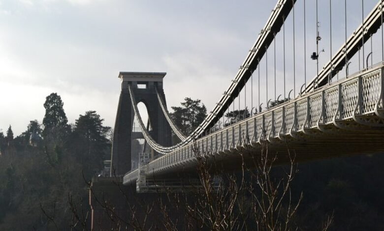
Suspension Bridge Design: 5 Proven Principles for Structural Stability
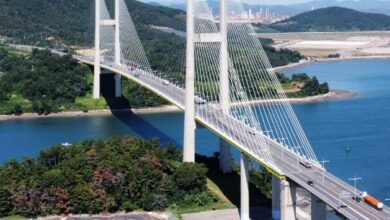
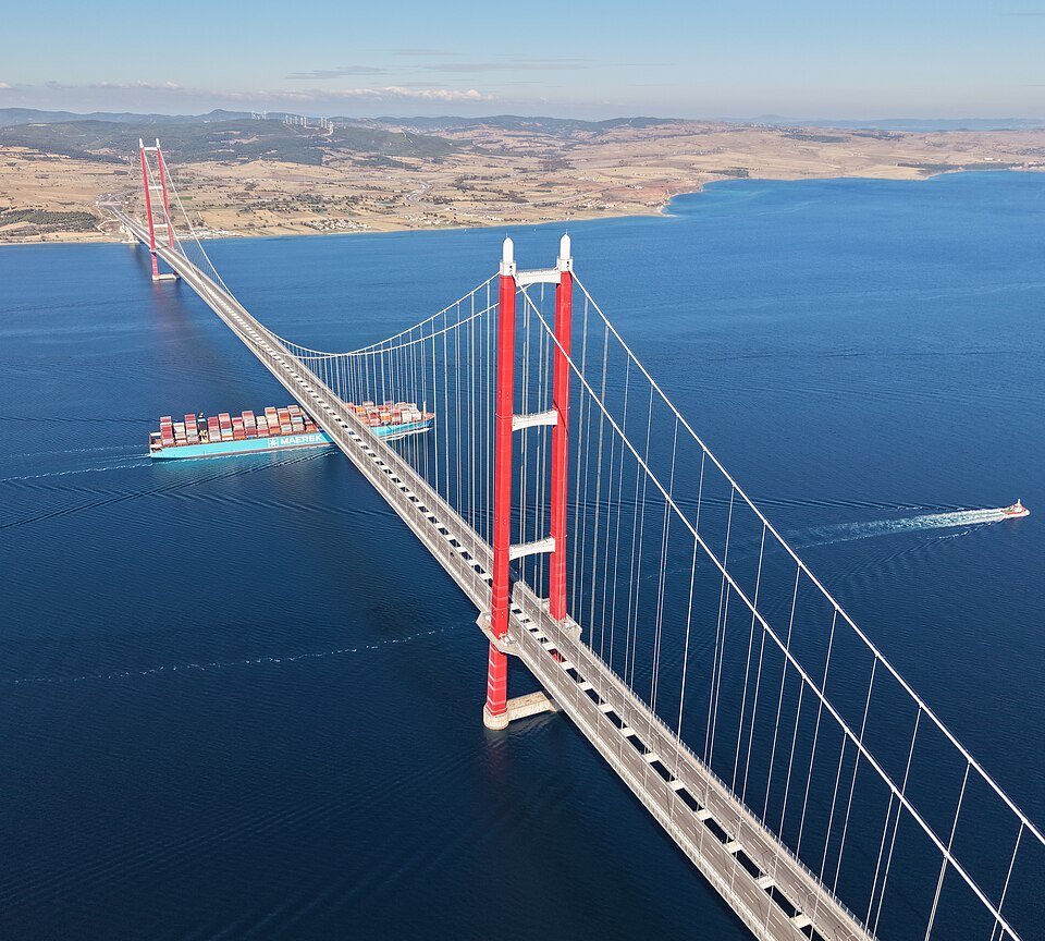
Suspension bridge design solves one problem above all others: how to carry a live, moving load across a gap too wide for any beam, arch, or truss to manage alone. Every element of a suspension bridge, from the deck to the anchorage buried in bedrock, exists to move force along a single continuous path. The 1915 Çanakkale Bridge in Türkiye now holds that record with a 2,023-metre main span, but the five principles behind it apply equally to a rural pedestrian crossing or a six-lane strait crossing.
Technical Snapshot: Core Suspension Bridge Design Parameters
| Element | Typical Function |
| Main Cable | Carries vertical load in pure tension, draped between towers |
| Hangers (Suspenders) | Transfer the deck load vertically into the main cable |
| Towers | Carry cable load in vertical compression to the foundation |
| Anchorages | Resist the horizontal pull of the main cable at each end |
| Stiffening Girder/Deck | Distributes live load and resists wind-induced deflection |
| Sag-to-Span Ratio | Typically 1:9 to 1:11, governs cable tension and tower height |
Get these five principles wrong, and a suspension bridge design fails long before it fails structurally, in cost overruns, wind instability, or a service life measured in decades rather than a century.
Introduction: Suspension Bridge Design
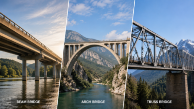
A suspension bridge looks simple from a distance: two towers, a pair of cables, and a deck hanging in between. The simplicity is deceptive. Suspension bridge engineering is one of the most demanding disciplines in structural practice because the entire system depends on tension, a force that steel handles well, but that concentrates enormous stress at every connection point. Unlike the compression-dominated logic covered in our piece on beam, arch, and truss bridge systems, sound suspension bridge design only works because its main cables naturally curve under load, then lock into that geometry through precise sequencing of suspension bridge construction.
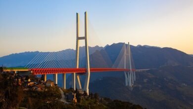
This article sits alongside our broader review of the world’s tallest bridges, where suspension designs dominate the record books precisely because no other system matches their capacity for load transfer in suspension bridges across such enormous unsupported distances. What follows are five suspension bridge design principles explained through the mechanics, materials, and benchmark projects that separate a stable structure from one that fights its own geometry for its service life.
Principle 1: Load Transfer Through the Cable, Tower, and Anchorage Chain
Suspension bridge structural stability begins with understanding that nothing in the system carries load independently. Every force applied to the deck, whether from traffic, wind, or the bridge’s own weight, travels through a fixed sequence of elements before it reaches the ground, and breaking that sequence anywhere costs the structure its equilibrium. This is how suspension bridges transfer load: a continuous handoff from tension to compression and back again, the single idea underpinning every other decision in suspension bridge design.
A stronger cable does nothing for the structural stability of suspension bridges if the tower beneath it or the anchorage behind it was sized for a lighter load; load transfer in suspension bridges only works when every link in the chain is sized to the same governing case.
The Deck-To-Hanger Connection
The stiffening girder or deck carries live and dead loads horizontally along its span. At regular intervals, vertical hangers, sometimes called suspenders, pick up that load and transfer it upward into the main cable. Hanger spacing is not arbitrary; closer spacing reduces local deck bending but adds fabrication and inspection cost, so designers balance the two against the project’s specific traffic loading and deck stiffness.
Compression Through the Towers
Once the load enters the main cable, it travels along the cable’s curve toward the towers. At the tower saddle, the cable’s vertical component pushes straight down into the tower structure, which resolves that force in pure compression down to the foundation. Suspension bridge towers are, in this sense, doing the same job as the piers of any bridge type, but at a scale and height that most compression members never approach. On the 1915 Çanakkale Bridge, suspension bridge towers rise to 334 metres, making them among the tallest bridge structures on earth while still functioning as simple compression columns at their core.
Tension Resolved at the Anchorages
The horizontal component of cable tension does not disappear at the tower; it continues past it toward the anchorages at each end of the bridge. This is the part of suspension bridge structural stability that is easiest to underestimate. A cable pulling with tens of thousands of tonnes of force needs a massive or deep enough anchorage to resist that pull indefinitely. Get the anchorage design wrong, and no amount of cable strength or tower height matters.
Further Reading: Beam, Arch, and Truss Bridges: 3 Essential Systems Powering Design
Principle 2: Main Cable Engineering as the Backbone of Stability
Suspension bridge cables do more work per tonne of material than almost any other structural element in civil engineering, because steel wire in tension can be stressed close to its full theoretical strength with minimal safety penalty. Suspension bridge cable engineering has developed its own specialised construction methods, metallurgy, and inspection regime, all built around keeping thousands of individual wires acting as one continuous unit. Get this second of the five principles wrong, and every downstream calculation, from tower height to anchorage mass, shifts along with it.
Parallel Wire Strand Versus Air-Spun Cables
Two methods dominate the engineering of suspension bridge cables. The aerial spinning (AS) method pulls individual wires back and forth across the span on a travelling wheel, building the cable strand by strand on site, a technique pioneered on American and European suspension bridges. The prefabricated parallel wire strand (PPWS) method fabricates complete strands in a factory, then hauls each finished strand into position and binds them together into the main cable.
PPWS uses the finished strand as its traction unit, while AS relies on each individual wire and only forms strands once work reaches the catwalk. PPWS now dominates in Japan and China because it shortens suspension bridge construction time and gives engineers tighter control over the final cable geometry, a real advantage once the main span exceeds 2 kilometres.
AS vs PPWS Main Cable Construction
| Factor | Air Spinning (AS) | Prefabricated Parallel Wire Strand (PPWS) |
| Traction Unit | Individual wire | Complete pre-assembled strand |
| Where Strands Form | On the catwalk, in the field | In the factory, before shipping |
| Tension Control | Harder to keep uniform across wires | Tighter, more consistent tension control |
| Construction Speed | Slower, multiple field passes | Faster, fewer field operations |
| Regional Prevalence | United States, Europe | Japan, China |
| Best Suited To | Remote sites, flexible design changes | Very long spans, high-precision geometry |
Sag-To-Span Ratio and Cable Geometry
The curve a main cable takes under load, its sag-to-span ratio, is one of the first decisions in any suspension bridge design. A deeper sag reduces cable tension for a given load but increases the cable length required and steepens the angle at the towers. Most long-span suspension bridges settle on a ratio between 1:9 and 1:11, balancing material efficiency against tower height and anchorage geometry. This single number cascades through every other calculation in suspension bridge cable engineering.
Wire Strength and Corrosion Protection
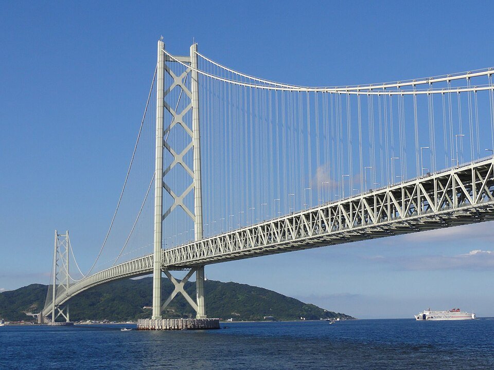
Modern suspension bridge cables rely on galvanised, high-tensile steel wire, each strand drawn down to roughly five millimetres in diameter to maximise tensile strength. The Akashi Kaikyo Bridge required a purpose-developed silicon-strengthened wire to achieve the strength its record span demanded, and its finished cables contain enough total wire length to circle the earth several times. Corrosion protection, typically galvanising combined with wrapping wire, paint systems, and increasingly dehumidified air injected directly into suspension bridge cables, determines whether that steel reaches its full design life or fails decades early.
Principle 3: Tower Design and Construction Sequencing
Suspension bridge towers carry more than dead weight. They resist the horizontal thrust transferred through the cable saddle, absorb seismic and wind loading, and on many coastal or strait crossings sit on foundations excavated tens of metres below the waterline before a single tower segment rises above it. Suspension bridge tower design and construction is therefore as much a foundation engineering exercise as a superstructure one, and it is where a large share of the total construction budget and schedule risk sits.
Steel Versus Concrete Towers
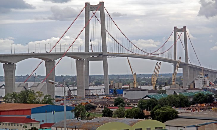
Most historic suspension bridges used riveted or welded steel towers, prized for their strength-to-weight ratio and speed of erection. Contemporary long-span designs increasingly favour reinforced or post-tensioned concrete suspension bridge towers, which offer better damping, lower long-term maintenance, and, where regional construction capacity is strong, a cost advantage over fabricated steel. Africa’s longest suspension bridge, the Maputo-Catembe Bridge in Mozambique, illustrates the concrete approach well: its two 137-metre towers sit on piled foundations reaching up to 100 metres deep, chosen specifically for the soft coastal soils around Maputo Bay.
Steel vs Concrete Suspension Bridge Towers
| Factor | Steel Towers | Concrete Towers |
| Strength-to-Weight | High, favours tall or seismic sites | Lower, but ample for most spans |
| Erection Speed | Fast, prefabricated sections bolted or welded | Slower, sequential pours or slip-forming |
| Damping Performance | Lower; needs supplementary dampers | Better inherent damping characteristics |
| Maintenance Profile | Ongoing corrosion protection required | Lower long-term maintenance |
| Typical Use Case | Record-span, high-wind crossings | Regions with strong local concrete capacity |
Foundation and Caisson Construction
Where towers must be founded underwater, engineers typically lower a fabricated steel caisson to the seabed, pump it dry, and fill it with concrete to create a stable platform before tower construction begins above the waterline. On the Akashi Kaikyo Bridge, this meant excavating foundations to depths comparable to those of a twenty-storey building before any visible structure appeared. Scour protection, usually graded stone covered in riprap, then guards the completed foundation against the tidal currents that made deepwater construction necessary in the first place.
Construction Sequencing From Foundation to Deck
Suspension bridge construction follows a strict sequence that cannot be compressed without compromising stability: foundations first, towers second, catwalks and main cables third, hangers fourth, and only then the deck segments, typically lifted from barges or launched outward from each tower. Reversing or overlapping these stages introduces geometry errors that are costly to correct once the main cable is erected, since a finished cable’s shape is very difficult to alter afterward. This sequencing discipline separates well-run suspension bridge construction from projects that run years over schedule.
Principle 4: Anchorage and Foundation Systems
An anchorage has one job: hold the end of the main cable in place against a pull that can reach tens of thousands of tonnes for the structure’s entire service life. Suspension bridge design treats anchorage sizing as a geotechnical problem as much as a structural one, since the ground beneath it ultimately determines how that force is resisted, a major factor in the structural stability of suspension bridges built on weak coastal soils.
Gravity anchorages remain the most common solution on major crossings. A massive block of reinforced concrete, sometimes exceeding 300,000 tonnes on the largest bridges, relies on its own dead weight and friction with the surrounding soil or rock to resist the pull of the cables. Where suitable bedrock is close to the surface, engineers can reduce concrete volume by anchoring directly into the rock. Self-anchored suspension bridges take a different approach, terminating the main cable into the stiffening girder rather than relying on a separate ground anchorage, which suits poor-soil sites but shifts extra compressive load onto the deck itself.
Gravity vs Self-Anchored Systems
| Factor | Gravity Anchorage | Self-Anchored System |
| Load Path | Cable pull resisted by anchorage mass | The cable terminates in the stiffening girder |
| Ground Requirement | Needs competent soil or rock | Suits poor or unpredictable ground |
| Material Volume | Very high, often 300,000+ tonnes | Lower anchorage mass, higher deck demand |
| Deck Impact | Minimal added compression | The deck carries an additional compressive load |
| Typical Application | Major strait and river crossings | Sites where ground anchorage is impractical |
Principle 5: Deck Stiffening and Aerodynamic Stability
A suspension bridge deck has to do two jobs that pull in opposite directions: stay light enough that the cables and towers are not overloaded, and stay stiff enough that wind cannot set it oscillating. Suspension bridge structural stability has historically been won and lost on this trade-off, and lessons from early failures still shape every long-span design produced today.
Stiffening girders, whether steel trusses or streamlined box girders, resist the torsional twisting that wind imposes on a long, flexible span. Truss-type girders, as detailed in our article on beam, arch, and truss bridges, let wind pass through the structure rather than load it as a solid surface, which is why many of the longest suspension bridges still favour open truss decks. The Akashi Kaikyo Bridge pairs a dual-hinged steel truss girder with tuned mass dampers to control resonance, allowing it to withstand wind speeds above 250 kilometres per hour without dangerous deflection.
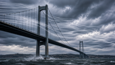
Every long-span suspension bridge design is now validated in a wind tunnel before construction begins, a practice adopted industry-wide after well-documented failures of early flexible-deck designs in the twentieth century. Our dedicated article on bridge aerodynamics and wind load engineering covers the testing methods and deck profiles used to prevent that failure mode from recurring. Suspension bridges are not the only long-span solution engineers reach for: our review of cable-stayed bridge design explains why that system is the fastest-growing alternative for mid-range spans, and our piece on extreme-environment bridge engineering covers how both adapt to seismic zones, high-altitude crossings, and severe marine conditions.
Further Reading: Cable-Stayed Bridges: 6 Reasons They’re the Fastest-Growing Design
Technical Block: Benchmarks in Global Suspension Bridge Design
Understanding suspension bridge structural stability in the abstract is one thing; seeing the five principles at work across the world’s longest spans grounds the discussion in built reality. The table below tracks the main span, tower height, and completion year of the benchmark projects referenced throughout this article.
| Bridge | Main Span | Tower Height | Completed |
| 1915 Çanakkale Bridge, Türkiye | 2,023 m | 334 m | 2022 |
| Akashi Kaikyo Bridge, Japan | 1,991 m | 283 m | 1998 |
| Maputo-Catembe Bridge, Mozambique | 680 m | 137 m | 2018 |
These three projects span three continents and four decades of suspension bridge engineering, yet each follows the same five principles: a continuous load path from deck to anchorage, precisely engineered main cables, towers sequenced from foundation upward, anchorages sized to local ground conditions, and a deck stiffened and wind-tested against the climate of its crossing.
Cable-stayed bridges remain practical only up to around one kilometre of span, which is why, among the longest suspension bridges in the world, suspension design owns every record-setting position on the list and why it remains the reference discipline for any crossing where distance, depth, or shipping clearance rules out every other bridge type.
Conclusion: Why These Five Principles Still Govern Every New Span
Suspension bridge design has not changed its fundamentals since the earliest wire-cable crossings of the nineteenth century; it has only refined how precisely each principle can be executed. Load transfer through the cable, tower, and anchorage chain remains the organising principle behind every new project. Cable engineering has moved from field-spun wire to factory-fabricated strand systems that shave months off schedules, tower design now reaches heights and foundation depths unthinkable a generation ago, and anchorage engineering has adapted to far poorer ground conditions than early designers would have accepted. Deck stiffening and aerodynamic testing, born of hard lessons in the twentieth century, are now standard practice on every long-span project.
For engineers, investors, and infrastructure planners evaluating a future crossing, the message is consistent: suspension bridge design succeeds or fails on these five principles working together, not on any single one in isolation. A flawless main cable paired with an undersized anchorage is just as vulnerable as a strong deck on an under-engineered tower foundation. The projects that make the record books, from the Dardanelles to the Akashi Strait to Maputo Bay, succeed because their engineers treated all five as non-negotiable.
Explore More of Bridge Engineering
From suspension bridges to record-breaking megaprojects, explore Construction Frontier: Engineering Fundamentals for expert technical analysis, engineering deep dives, and project reviews of the world’s most remarkable bridge designs.