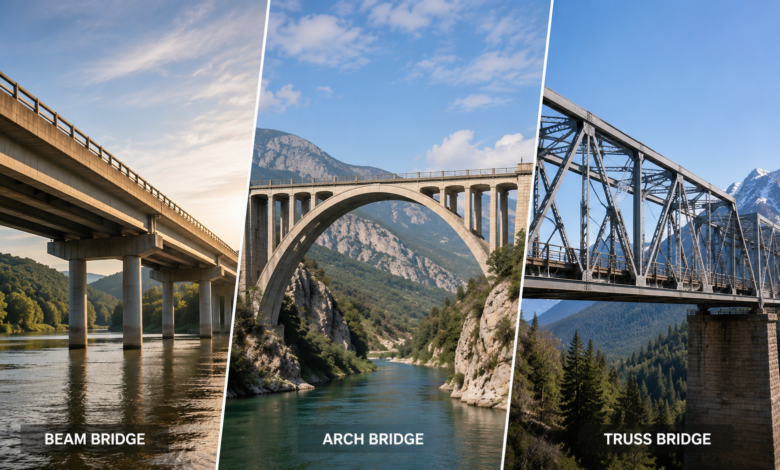
Beam, Arch, and Truss Bridges: 3 Essential Systems for Stronger Bridge Design
Beam, arch, and truss bridges form the structural foundation of nearly every road, rail, and pedestrian crossing built worldwide. Each system resolves the same problem by safely transferring vertical load to the ground through a different internal force pattern: bending in beams, compression in arches, and triangulated tension and compression in trusses. Engineers select between these three structural systems based on span length, site geometry, material availability, and budget, with truss configurations extending economical spans to roughly 400 metres and arch systems pushing beyond 500 metres in steel and concrete.
Technical Snapshot: Core Structural System Specifications
| Specification | Detail |
| Beam bridge typical span range | 10 to 50 metres, extendable with prestressing and continuous spans |
| Arch bridge typical span range | 100 to 800 metres, depending on material and rise-to-span ratio |
| Truss bridge typical span range | 80 to 400 metres |
| Beam bridge dominant force | bending, producing top-fibre compression and bottom-fibre tension |
| Arch bridge dominant force | axial compression transferred outward to the abutments |
| Truss bridge dominant force | axial tension and compression isolated within individual triangulated members |
| Primary materials | steel, reinforced concrete, prestressed concrete, timber (historic truss forms) |
| Common configurations | simply supported and continuous beams; deck, through, and tied arches; Pratt, Warren, and Howe trusses |
Choosing correctly among beam, arch, and truss bridges determines whether a crossing meets its span, load, and lifecycle cost targets, making this comparison one of the most consequential early decisions in any bridge engineering programme.
Introduction: Beam, Arch, and Truss Bridges Structural Systems
Every bridge engineering programme begins with a structural systems decision, and beam, arch and truss bridges represent the three fundamental types of bridge structures that engineers return to again and again. These remain the most common types of bridge structures in active use because they predate cable-stayed and suspension technologies, are well understood, and readily adapt to local materials. Readers who want to see these bridge engineering fundamentals pushed to a record-breaking scale can review the engineering behind some of the tallest bridge structures ever built.
This article works through beam bridge engineering, arch bridge design, and truss bridge design principles in turn, then directly compares all three systems in terms of span, load behaviour, material efficiency, and cost. Understanding the differences among beam, arch, and truss bridges from first principles is a fundamental concept in bridge engineering that every project professional should grasp before selecting a structural type.
Beam Bridge Engineering: Simplicity and Load Transfer
Beam bridge engineering is the starting point among the three fundamental types of bridge structures, because a beam is the simplest possible way to span a gap: a horizontal member resting on two supports. This section covers how beam bridges distribute loads internally, the materials and span limitations that constrain beam bridge design, and the construction methods contractors use to erect them efficiently.
How Beam Bridges Distribute Load
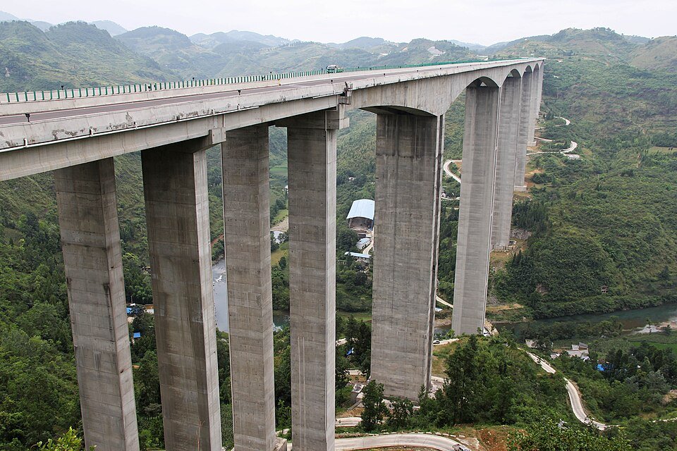
When traffic loads a beam bridge deck, the beam bends. This is the same underlying tension-and-compression bridge behaviour that governs every structural system compared in this article, expressed here as top-fibre compression and bottom-fibre tension along the span. Bending is greatest at mid-span, and shear is greatest near the supports. The beam then transfers this internal force pattern down through piers or abutments, which sit in compression, into the foundation.
Load distribution also depends on how the beams are connected. Continuous beam configurations distribute loads more evenly than simply supported spans, since continuity transfers forces across multiple spans rather than terminating at each support, which is why continuous multi-span beam bridges carry heavier, more variable traffic than a series of independent simple spans.
Materials and Span Limitations in Beam Bridge Design
Beam bridge engineering is bounded by a straightforward relationship between span, depth, and material strength. Steel and prestressed concrete dominate modern construction because both offer high strength relative to self-weight, allowing longer spans before the beam’s own mass becomes the controlling load. Reinforced concrete suits shorter urban spans where formwork favours cast-in-place work, while timber persists for rural, low-traffic crossings where local supply and cost outweigh reduced spans.
Unstiffened beam bridge engineering is generally most efficient for spans of roughly 50 metres or less. Beyond that point, required beam depth grows disproportionately to the material saved, which is why longer spans shift toward continuous girders, prestressed sections, or a different system entirely, sometimes a truss, and beyond a few hundred metres, a tension-based system such as the suspension bridge.
Beam Bridge Construction Methods
Beam bridge construction methods fall into two dominant categories, and the choice shapes programme duration and site disruption. Precast beams, cast off-site to controlled tolerances, are lifted into position by crane, compressing schedules and limiting traffic interruption. Cast-in-place construction remains preferable for irregular spans or constrained access. Both methods depend on accurate substructure work, since pier and abutment placement fixes the load path the beams must carry.
Beam Bridge Construction Method Comparison
| Construction Method | Fabrication Location | Programme Impact | Best-Suited Conditions |
| Precast beams | Off-site, controlled plant conditions | Compressed schedule; limited traffic disruption | Standardised spans, active corridors, good crane access |
| Cast-in-place | On-site formwork and pour | Longer schedule; greater site disruption | Irregular spans, constrained access, complex geometry |
Arch Bridge Design: Compression as a Structural Strategy
An arch bridge design solves the same span problem as a beam bridge, but through a different force pattern. Rather than bending, the arch converts vertical load into axial compression that travels along the structure’s curve to the abutments. This section explains how arch bridges distribute load through compression, reviews the deck configurations engineers choose between, and sets out the span and material considerations that govern arch bridge design.
How Arch Bridges Distribute Load Through Compression
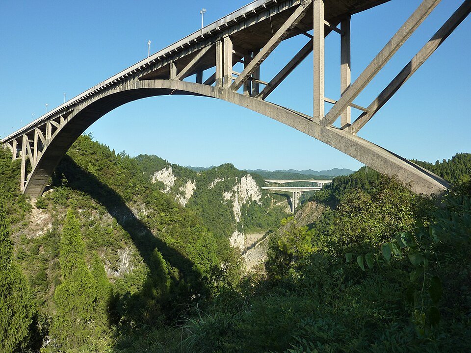
An arch bridge works by converting the vertical loads acting on the structure into a horizontal thrust that travels along the curve to the abutments at each end. Every stone, precast segment, or steel rib is held in place by the compressive force of the material pushing against its neighbours, which is why arch bridges have historically used materials strong in compression but weak in tension, such as stone, brick, and unreinforced concrete. Modern steel and reinforced-concrete arches extend this same logic to far greater spans than historic masonry arches could.
Because the arch pushes outward as well as downward, the abutments carry both vertical and horizontal reactions. Site geology becomes a governing factor: arch bridges perform best where foundations resist horizontal thrust without excessive movement, which is why river gorges and rock-faced valleys have historically been favoured sites.
Deck Arch, Through Arch, and Tied Arch Configurations
Arch bridges are classified primarily by where the roadway sits relative to the arch, and each configuration changes how the load reaches it. A deck arch places the roadway entirely above the arch, with load transferred down through vertical columns, suited to valleys or rivers with ample clearance below. A through arch instead carries the deck partway up the arch’s height, suspended from the ribs above, for sites with limited vertical clearance. A tied arch addresses a further constraint: a weak foundation material that cannot resist horizontal thrust. A tension member along the deck absorbs that thrust internally rather than passing it into the abutments, extending arch bridge design to sites where ground conditions would otherwise rule it out.
Arch Bridge Configuration Comparison
| Configuration | Deck Position | Load Path to Arch | Best-Suited Site |
| Deck arch | Entirely above the arch | Vertical columns down to the arch ring | Deep valleys or gorges with clearance below |
| Through arch | Partway up the arch height | Deck suspended from arch ribs | Sites with limited vertical clearance |
| Tied arch | At or near the arch springing line | Horizontal thrust absorbed by a deck-level tie | Weak foundations unable to resist thrust |
Span Capacity and Material Suitability
Arch bridges span further than beam bridges and, in steel construction, further than most truss bridges. Spans typically range from roughly 100 to 800 metres, with historic stone arches and modern steel arches, such as Sydney’s 503-metre harbour crossing, applying the same compression principle at very different scales. Concrete arches suit moderate spans with favourable local aggregate economics, while steel arches extend toward the upper span range for major river and gorge crossings, competing at that scale with cable-stayed structures where a single long span beats intermediate piers.
Further Reading: Cable-Stayed Bridges: 6 Reasons They’re the Fastest-Growing Design
Truss Bridge Design Principles Explained
Truss bridge design principles rest on a single geometric fact: a triangle cannot change shape without changing the length of its sides. This section explains how triangulation converts bending into axial forces, surveys common truss configurations used in bridge engineering, and reviews the span range and construction advantages that make truss bridges a durable choice for medium-span crossings.
Triangulation and Axial Force Distribution
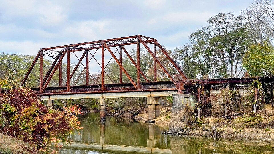
Trusses gain their strength through the triangulation of structural elements, with the triangle acting as an inherently stable form that distributes force along each diagonal without changing shape. Each member is idealised as pin-connected at its ends, and loads are applied at the joints rather than along the member’s length, keeping each piece in either pure tension or pure compression rather than in bending.
This channels the complex loads crossing a truss bridge into simple, straight-line forces, making them predictable and allowing engineers to size each component to its specific axial demand rather than a uniform worst case. This is the central efficiency advantage a truss holds over a solid beam of equivalent span: material goes only where structurally needed, with slender tension members replacing a single continuous section sized for the maximum bending moment.
Common Truss Configurations: Pratt, Warren, and Howe
Truss bridge design has produced several named configurations, each distributing tension and compression differently across the panel. The Pratt and Howe configurations appear visually identical, a repeated series of rectangles with diagonal crosses, but the two historic truss patterns place opposite members in tension: a Howe truss puts its diagonals in compression, and its verticals in tension, and a Pratt truss reverses that pattern.
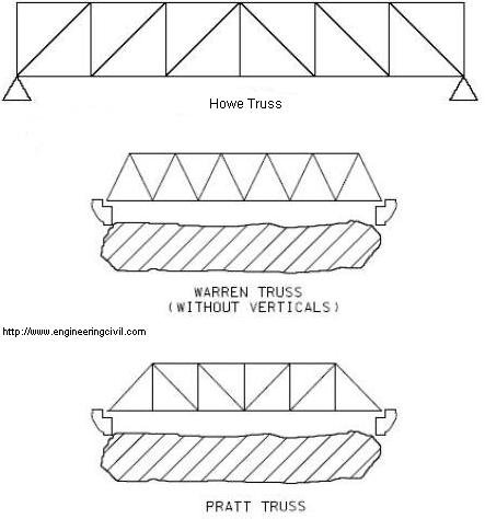
The distinction mattered historically, since it determined which members needed to be timber, suited to compression, and which needed iron or steel rods, suited to tension. The Warren truss instead uses equilateral triangles without vertical members in its simplest form, spreading load more evenly and minimising connection points, which is why it now dominates modern steel truss bridge construction.
Pratt, Howe, and Warren Truss Configuration Comparison
| Configuration | Diagonal Members | Vertical Members | Typical Historical Use |
| Pratt truss | Tension | Compression | Iron and steel bridges from the mid-1800s onward |
| Howe truss | Compression | Tension | Timber bridges, diagonals suited to wood in compression |
| Warren truss | Alternating tension and compression | Often absent in the simplest form | Modern steel bridges, minimal connection points |
Span Range and Prefabrication Advantages
Truss bridges are efficient for medium spans, roughly 80 to 400 metres, positioning the system between beam bridges and long-span arch structures. Within that range, a truss typically uses less material than a solid beam of the same span, since triangulation carries load more efficiently than bending. Truss components also lend themselves to prefabrication off-site to close tolerances, then bolted or welded together on-site, a method that shortens programme duration for remote crossings, including many of the sites covered by extreme-environment bridge engineering, where large monolithic sections would be impractical to transport.
Beam, Arch, and Truss Bridge Structural Systems Compared
With beam, arch and truss bridge structural systems compared side by side, it becomes clear why no single system dominates bridge engineering: each optimises for a different combination of span, site condition, and material economy. This section compares the three systems in terms of span, load behaviour, and material efficiency, and then sets out the practical factors that engineers weigh when choosing the right bridge structural system for a project.
Span, Load Behaviour, and Material Efficiency
Beam bridges remain the most economical choice for short spans, generally under 50 metres, because their construction is simple and maintenance is predictable. Their limitation is bending: as the span increases, the required depth grows faster than the material saved, making beams inefficient once an arch or truss becomes viable.
Arch bridges extend furthest at scale, particularly in steel, but demand foundation conditions capable of resisting horizontal thrust; where geology cannot support that thrust without a tied arch, the added cost can erode the arch’s material efficiency. Truss bridges occupy the middle ground, matching or exceeding beam bridge spans while using less material through triangulated axial force distribution, and they tolerate a wider range of foundation conditions than arches because they generate little horizontal thrust at the supports.
Beam, Arch, and Truss Bridge Structural Systems Compared
| System | Typical Span Range | Dominant Force | Foundation Demand | Material Efficiency at Span |
| Beam bridge | 10 to 50 metres | Bending (compression and tension) | Moderate; vertical reaction only | High for short spans, falls off beyond ~50 m |
| Arch bridge | 100 to 800 metres | Axial compression | High; must resist horizontal thrust | High at scale where geology allows |
| Truss bridge | 80 to 400 metres | Axial tension and compression | Moderate; little horizontal thrust | High across the medium-span range |
Choosing the Right Bridge Structural System for a Project
Choosing the right bridge structural system starts with span and site geology, but rarely ends there. Fabrication capacity, transport access, schedule, and maintenance budgets all weigh into the decision. A remote crossing with limited heavy-lift access may favour a prefabricated truss bridge assembled from smaller components, even where an arch would otherwise offer a more elegant span solution. A crossing with strong bedrock abutments and a requirement for minimal intermediate piers, by contrast, may favour an arch despite its higher design and falsework complexity.
Project professionals evaluating beam, arch, and truss bridges should treat span capability as a starting filter, since systems frequently overlap in feasible span ranges, and the deciding factors become site-specific cost, constructability, and maintenance profile rather than structural capacity alone.
Technical Block: Structural Selection Criteria for Bridge Engineering Programmes
This closing section translates the principles of beam, arch, and truss bridges above into a project-ready decision framework.
1. Match Structural System to Span and Foundation Conditions First
Span length and foundation capacity should narrow the shortlist first. A short span with firm, shallow bedrock keeps a beam bridge or short-span truss on the table; a wide gorge with strong abutment rock favours an arch; a medium span over soft ground favours a truss or tied arch. Once span and geology settle the shortlist, longer, more slender spans also raise questions about wind response and aerodynamic stability that shorter beam and truss crossings rarely need to address in detail.
2. Weigh Fabrication Access and Lifecycle Maintenance Together
Remote sites with limited crane capacity favour smaller, prefabricated components, typically a truss bridge over a monolithic arch or long beam. Urban sites with strong logistics networks can absorb the larger precast elements that beam and arch bridges often require. Maintenance matters too: steel trusses demand ongoing corrosion protection at many connection points, while concrete arches and beams demand less frequent but more disruptive maintenance, such as deck resurfacing or joint replacement.
Further Reading: Bridge Aerodynamics: 5 Powerful Solutions That Prevent Collapse
Conclusion: Matching Structural System to Project Demands
Beam, arch and truss bridges are not competing technologies so much as three answers to the same question: how does a structure move load from a deck to the ground across an open span? Beam bridge engineering remains unmatched for short, economical crossings; arch bridge design remains the system of choice where geology allows long single spans; and truss bridge design principles deliver a material-efficient, prefabrication-friendly solution across the medium-span range. The difference between beam, arch, and truss bridges comes down to how each carries loads: bending in beams, compression in arches, and triangulated tension and compression in trusses. That difference is the foundation on which every further bridge engineering fundamental decision is built.
Among all the types of bridge structures engineers choose from, these three fundamental bridge engineering systems account for most crossings built, precisely because their load paths are well understood and their failure modes are predictable.
For engineers and project professionals working across Africa’s expanding transport programmes, this comparison of bridge structural systems is not academic. Site geology varies widely across river basins, rift valleys, and coastal deltas, and the difference between a well-matched and a poorly matched structural system shows up directly in construction costs, programme duration, and decades of maintenance spending. Treating the selection of beam, arch, and truss bridges as an early, deliberate decision is what separates crossings built for their true design life from those that require premature intervention.
Explore More of Bridge Engineering
Beam, arch, and truss bridges are the foundation of modern bridge design. Explore Construction Frontier: Engineering Fundamentals Bridges for expert technical analysis, engineering deep dives, and project reviews covering bridge structural systems, construction methods, and the world’s most remarkable bridge-engineering achievements.