Top Construction Trade Shows to Watch in 2026: Essential Events Shaping the Industry’s Future
The world’s leading construction trade shows in 2026 will spotlight cutting-edge technologies, sustainable building solutions, and infrastructure innovations reshaping global project delivery. From electrified heavy machinery and AI-powered project controls to low-carbon cement and modular construction systems, the top construction trade shows to watch in 2026 will serve as high-level decision environments where contractors evaluate capital equipment, investors track infrastructure pipelines, and policymakers benchmark regulatory direction. For industrial leaders across engineering, finance, and construction, the 2026 construction trade show calendar is not a marketing itinerary; it is a strategic roadmap.
Introduction: Why Construction Trade Shows Matter More Than Ever
Construction trade shows have evolved into strategic convergence platforms where technology, capital, and policy intersect. In 2026, their influence will be more pronounced than at any time in the past decade.
- The evolving role of construction trade shows in a post-pandemic, tech-driven industry
In the aftermath of global supply chain disruptions and accelerated digital adoption, construction industry events have transitioned from exhibition halls into integrated ecosystems. Contractors no longer attend solely to compare machinery; they attend to evaluate integrated digital solutions, supplier resilience, lifecycle cost efficiencies, and ESG compliance.
Major construction exhibitions worldwide now integrate live demonstrations, digital twin simulations, infrastructure financing panels, and sustainability forums into a single event architecture. The result is a multidimensional environment where operational, financial, and regulatory considerations converge.
- Why 2026 is a pivotal year for global construction, infrastructure, and energy transition
The year 2026 marks a consolidation phase following heavy infrastructure stimulus in multiple regions. Governments are advancing transport corridors, renewable energy grids, water security systems, and urban housing at scale. At the same time, climate commitments and regulations on embodied carbon are tightening.
The construction expo 2026 cycle will therefore reflect three converging forces:
- Infrastructure expansion across emerging and developed markets.
- Decarbonisation and energy transition mandates.
- Technology-driven productivity imperatives.
This convergence underscores the strategic relevance of scheduling planning for global construction trade shows.
- How trade shows influence procurement decisions, technology adoption, and policy direction
Procurement cycles for heavy equipment, digital platforms, and prefabrication systems increasingly begin at major trade shows. Contractors test equipment performance under live conditions. Engineering teams assess interoperability with BIM and digital twin systems. Developers evaluate lifecycle carbon metrics before committing to material specifications.
Simultaneously, regulators and industry associations use these forums to align standards, emissions frameworks, and procurement criteria. As a result, construction trade shows exert measurable influence on both project-level decisions and national infrastructure strategies.
- The value of in-person networking versus digital construction platforms
While digital platforms support continuous engagement, in-person participation remains critical for high-value negotiations and technical validation. A 30-minute on-site demonstration of autonomous equipment or prefabrication systems often accelerates decision-making more effectively than months of remote discussions.
In 2026, hybrid engagement models will enhance reach, but the strategic centre of gravity will remain the physical exhibition floor.
Top Construction Trade Shows to Watch in 2026 (Global Overview)
The 2026 construction trade show calendar is anchored by a set of globally influential expos that shape procurement cycles, technology standards, and infrastructure investment trends. These are not routine construction industry events; they are platforms for initiating capital allocation decisions, equipment rollouts, regulatory alignment, and megaproject partnerships.
Below are the major construction expos and events in 2026 that will define the global construction landscape.
1. Bauma (Germany) & CONEXPO-CON/AGG (USA): Global Heavy Equipment Leadership
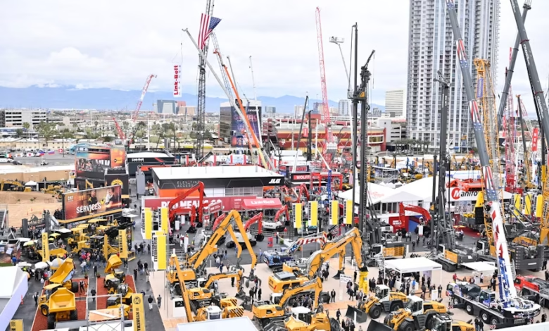
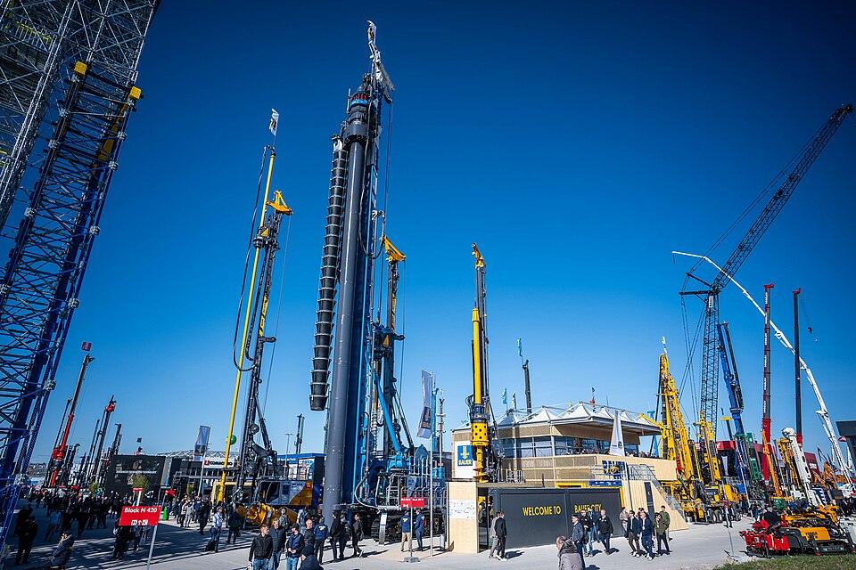
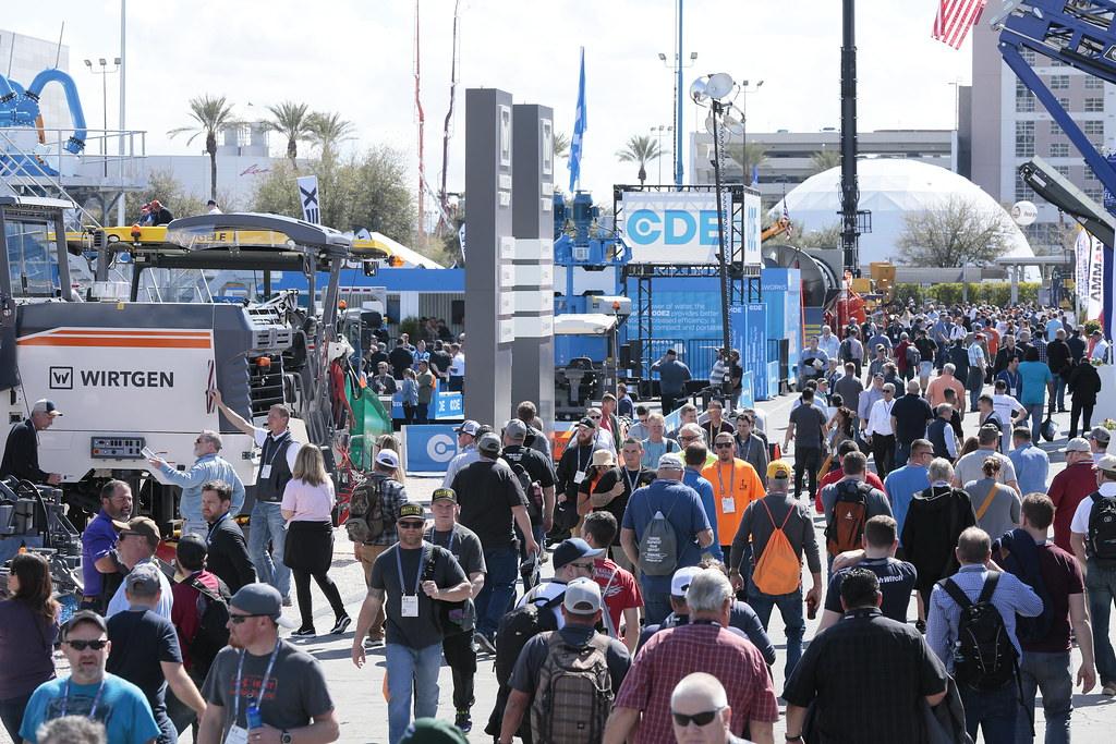
The Bauma and CONEXPO-CON/AGG expos remain the most influential construction equipment exhibitions globally in 2026, setting technical and commercial benchmarks for earthmoving, mining, aggregates, and infrastructure machinery.
Strategic significance in 2026:
- Launch of electric and hydrogen-powered heavy equipment fleets.
- Autonomous haulage and semi-autonomous earthmoving systems.
- Advanced telematics and predictive maintenance integration.
- Hybrid drivetrain solutions for emissions compliance.
Original Equipment Manufacturers (OEMs) use these platforms to unveil next-generation machinery aligned with decarbonisation mandates and fuel cost volatility. Contractors managing large infrastructure pipelines attend to evaluate the total cost of ownership (TCO), equipment productivity ratios, maintenance cycles, and emissions performance under tightening regulatory frameworks.
Procurement decisions worth hundreds of millions of dollars frequently originate from on-site demonstrations at these events. For firms operating across transport corridors, mining projects, and urban megaprojects, these expos define fleet strategy for the next five to ten years.
Events Dates:
- bauma (Germany): the event is not happening in 2026, but the next Bauma Munich (2028) is expected to open in Spring 2026.
- bauma CONEXPO INDIA 2026: September 28 – October 1, 2026, at the India Expo Centre, Greater Noida/Delhi.
- bauma CHINA 2026: November 24–27, 2026, at the Shanghai New International Expo Centre.
- CONEXPO-CON/AGG (USA): March 3–7, 2026, at the Las Vegas Convention Centre (LVCC) and Las Vegas Festival Grounds.
2. The Big 5 Global (UAE) & World of Concrete (USA): Building Materials and Advanced Construction Systems
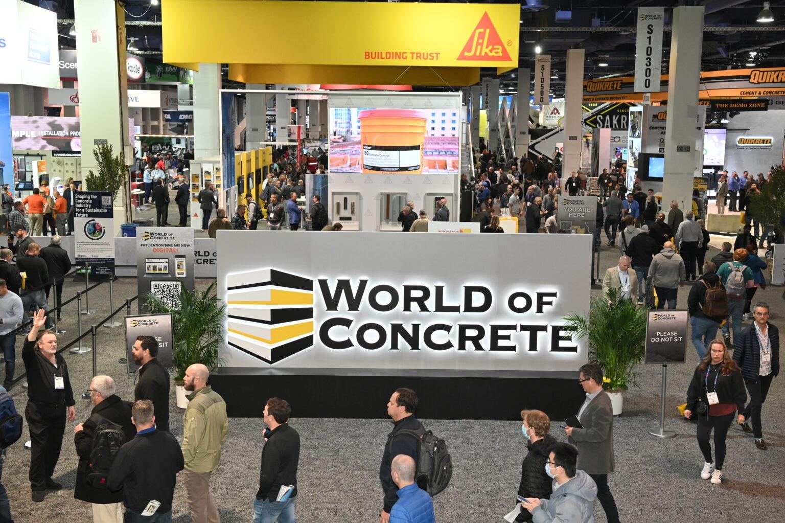
The Big 5 Global and World of Concrete are the leading construction technology trade shows in 2026, focusing on cement innovation, steel fabrication, prefabrication systems, and material science advancements shaping global infrastructure delivery.

Core themes for 2026:
- Low-carbon cement and supplementary cementitious materials (SCMs).
- Precast and modular construction systems.
- Smart materials with embedded IoT monitoring.
- Digitised construction supply chains.
As embodied carbon regulations tighten across Europe and North America, and green procurement standards expand globally, these expos influence material specification decisions at scale. Developers and quantity surveyors evaluate lifecycle carbon performance, cost stability, and availability across supply chains.
Given the rising demand for off-site construction methods, modular and prefabrication systems showcased at these events directly impact housing, healthcare, and commercial infrastructure projects worldwide.
Events Dates:
- Big 5 Global (UAE): November 23–26, 2026, at the Dubai World Trade Centre (DWTC).
- World of Concrete (USA): took place from January 19-22,2026, at the Las Vegas Convention Centre (LVCC). As this event has just concluded, the next edition is already scheduled for January 18–21, 2027.
3. MIPIM (France): Infrastructure Capital and Urban Megaproject Alignment
Although positioned as a real estate and urban development forum hosted in Cannes, MIPIM (Marché International des Professionnels de l’Immobilier) plays a critical role in shaping infrastructure capital flows and long-term construction pipelines.

Why it matters in 2026:
- Public-private partnership (PPP) structuring discussions.
- Infrastructure debt and equity financing alignment.
- Climate-resilient urban master planning.
- Transit-oriented development investment.
For developers, sovereign wealth funds, and infrastructure investors, this is where capital meets pipeline. Contractors and engineering firms use this platform to secure early-stage alignment on multibillion-dollar transport, mixed-use, and smart city projects.
Within the global construction trade shows schedule, MIPIM stands out as a financing-driven catalyst rather than a machinery showcase, making it essential for leaders focused on infrastructure capital strategy.
Event Dates:
- MIPIM (France): the expo is scheduled for March 9-13, 2026, at the Palais des Festivals, Cannes, France.
4. Greenbuild International Conference and Expo (USA): Sustainability, ESG, and Net-Zero Construction
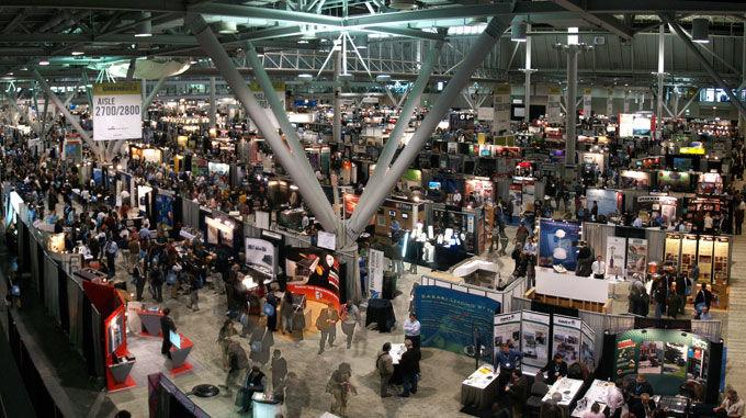
As sustainability mandates intensify, Greenbuild International Conference and Expo remains one of the most strategically relevant construction exhibitions worldwide for decarbonisation and ESG integration.
2026 focus areas include:
- Net-zero building design and certification pathways.
- Embodied carbon disclosure frameworks.
- Circular construction methodologies.
- Climate adaptation engineering.
Public agencies and institutional investors increasingly require ESG compliance across infrastructure projects. This expo influences global specification frameworks, carbon accounting methodologies, and procurement policies.
For firms competing in markets with strict environmental regulations, participation is no longer optional; it is a compliance and competitiveness imperative.
Event Dates:
- Greenbuild International Conference and Expo (USA): the event is scheduled for October 20-23, 2026, at the Jacob K. Javits Convention Center in New York City.
5. Regional Powerhouses in the Global Construction Trade Shows Schedule
Beyond flagship global expos, several regional events significantly shape regional infrastructure and construction ecosystems.
(i) Europe: INTERMAT (France)
INTERMAT emphasises advanced machinery, robotics, electrification, and decarbonised equipment systems. Europe’s regulatory leadership in emissions and sustainability standards often sets precedents later adopted globally.
Event Dates:
- There is no INTERMAT exhibition scheduled for 2026. Like Bauma Germany, INTERMAT follows a three-year cycle and was last held in April 2024 at Paris Nord Villepinte, France.
(ii) Asia: Bauma China (China)
As Asia continues to lead in megaproject scale and manufacturing output, Bauma China provides insight into regional production capacity, supply chain strength, and the acceleration of urban infrastructure.
Event Dates:
- bauma China will be held on November 24–27, 2026, at the Shanghai New International Expo Centre.
(iii) Middle East: Saudi Build (Saudi Arabia)
Driven by giga-projects and sovereign-backed infrastructure expansion, Saudi Build reflects the rapid transformation underway in the Middle East’s construction sector.
Event Dates:
- The Saudi Build 2026 exhibition is scheduled to take place from November 2-5, 2026, at the Riyadh International Convention & Exhibition Centre (RICEC), Riyadh, Saudi Arabia.
(iv) Africa: BuildExpo Africa
As infrastructure corridors expand, housing demand grows, and energy transition investments increase, African construction expos such as BuildExpo Africa highlight regional supplier networks, expanded equipment distribution, and emerging project pipelines.
Event Dates:
- Buildexpo Kenya 2026: held on July 8–10, 2026, at the Kenyatta International Convention Centre (KICC), Nairobi, Kenya.
- Buildexpo Tanzania 2026: held on September 23–25, 2026, at the Diamond Jubilee Expo Centre, Dar es Salaam, Tanzania.
Strategic Takeaway
These top construction trade shows to watch in 2026 collectively define the innovation, capital allocation, sustainability standards, and procurement strategies shaping the global industry.
For industrial leaders across engineering, contracting, project finance, and public infrastructure, attending and participating in the right construction trade shows is a strategic lever, not a discretionary activity.
How Construction Trade Shows Shape the Global Industry
Construction trade shows operate as accelerators of structural change across the construction value chain. They influence innovation trajectories, supply chain realignment, and the integration of sustainability at scale. Let’s check into some of the ways construction trade shows impact the global construction industry.
1. Driving Innovation and Technology Adoption
Construction technology trade shows 2026 will act as global launchpads for:
- AI-powered project scheduling platforms such as Autodesk Construction Cloud, Open Space AI, Procore, and Buildots.
- Integrated BIM and digital twin ecosystems.
- Robotics for rebar tying, bricklaying, and inspection.
- IoT-enabled asset tracking and predictive maintenance.
Live demonstration environments distinguish scalable solutions from conceptual prototypes. When robotics systems operate on simulated job sites or digital platforms that integrate with real project data, contractors can evaluate deployment readiness with precision.
For deeper insights by Construction Frontier into digital transformation trends shaping these showcases, read the following:
- Why BIM (Building Information Modelling) Matters in Africa: An Essential Guide to Smarter Construction
- 10 Ultimate Digital Twins Applications in Construction: Revolutionising Smart Building Performance
Early exposure allows firms to pilot technologies before they become industry standards, securing a competitive advantage in cost control and productivity.
2. Connecting Global Markets and Supply Chains
Global construction trade shows connect original equipment manufacturers (OEMs), material suppliers, developers, infrastructure funds, and government agencies within a single transactional environment.
These interactions frequently catalyse:
- Cross-border joint ventures.
- Equipment distribution agreements.
- Infrastructure financing partnerships.
- Technology licensing arrangements.
Given the capital-intensive nature of infrastructure, early engagement between contractors and financiers often begins during major construction expos and events in 2026 and beyond.
3. Influencing Policy, Standards, and Sustainability Goals
Sustainability and ESG (Environmental, Social & Governance) compliance are now core pillars of programming at major construction industry events. Panels address:
- Carbon disclosure requirements.
- Low-carbon cement standards.
- Lifecycle assessment frameworks.
- Green procurement policies.
These discussions shape regulatory environments and inform how public agencies structure future tenders. As decarbonisation becomes embedded in procurement criteria, trade shows serve as transitional arenas where industry aligns with evolving policy frameworks.
Key Trends Defining Construction Trade Shows in 2026
The 2026 exhibition cycle will reflect broader structural transformations in the construction industry. Several defining themes will dominate the best construction trade shows 2026.
1. Digital Construction and Smart Job Sites
Digital integration is no longer optional. BIM interoperability, real-time analytics dashboards, and digital twin integration will define technology pavilions. AI-powered risk forecasting and automated progress tracking systems will be demonstrated as deployable solutions rather than experimental concepts.
Smart job sites equipped with sensors, drones in construction, and integrated data platforms represent the operational frontier of productivity enhancement.
2. Sustainable Construction and Green Materials
Low-carbon cement alternatives, geopolymer technologies, recycled steel inputs, and modular timber systems will anchor sustainability zones. Lifecycle carbon accounting tools will be embedded within procurement software demonstrations.
For expanded context:
- What Is Green Building Technology? Definition, 5 Benefits, and Applications
- Top 15 Green Building Materials: Sustainable Choices for a Better Future
Green building certifications and ESG reporting standards will influence specification decisions across both public and private projects.
3. Heavy Equipment Innovation and Electrification
Construction equipment exhibitions in 2026 will feature electrified excavators, battery-powered loaders, and hydrogen-powered machinery. Autonomous haulage systems and semi-autonomous grading equipment will be demonstrated under controlled conditions.
Electrification aligns with tightening emissions regulations, especially in Europe and parts of Asia, and addresses rising fuel cost volatility.
4. Infrastructure and Megaproject Development
Transport corridors, smart cities, renewable energy infrastructure, and water security systems will feature prominently. Public-Private Partnerships (PPPs) and infrastructure funds will use these platforms to announce investment pipelines.
Related reading: Top 10 Outstanding Smart Cities Leading the Future of Urban Innovation
Why Construction Professionals Should Attend Trade Shows in 2026
Participation in major construction trade shows yields measurable business outcomes for stakeholders.
For Contractors and Engineers
- Evaluate equipment productivity under live conditions.
- Compare automation and digital integration platforms.
- Benchmark safety and emissions performance.
Skills development sessions and technical forums also provide critical workforce insights for long-term competitiveness.
For Developers and Investors
- Access early visibility into infrastructure pipelines.
- Engage OEMs and technology providers.
- Identify emerging construction technologies with scaling potential.
These forums offer real-time intelligence unavailable through secondary reporting.
For Policymakers and Public Agencies
- Benchmark infrastructure delivery models.
- Evaluate sustainable construction technologies.
- Align procurement standards with global best practices.
Trade shows provide neutral platforms for public-private dialogue.
How to Choose the Right Construction Trade Show to Attend
Selecting from the global construction trade shows schedule requires disciplined strategic alignment. Not every construction expo 2026 delivers equal value to every organisation. For contractors, developers, engineering consultants, equipment distributors, and policymakers, the decision must be driven by capital planning cycles, market expansion objectives, and technology transformation priorities.
In 2026, with dozens of major construction expos and events across Europe, Asia, the Middle East, Africa, and North America, choosing the right ones can materially influence procurement efficiency, partnership development, and competitive positioning.
1. Aligning Trade Shows with Business Goals
The first filter in choosing among construction trade shows is strategic intent. Firms should clearly define whether their primary objective is:
- Fleet renewal and equipment benchmarking.
- Digital construction transformation.
- Market expansion into new regions.
- Supplier diversification.
- Infrastructure financing engagement.
For example, contractors planning significant capital expenditure on heavy machinery should prioritise construction equipment exhibitions 2026, such as Bauma or CONEXPO. Firms focused on modular housing, low-carbon materials, or offsite construction should prioritise building-materials-focused construction industry events.
Similarly, engineering consultancies exploring BIM integration, digital twins, and AI-powered analytics should attend construction technology trade shows in 2026, where interoperability and live platform demonstrations can be assessed.
Without alignment to defined business outcomes, attendance risks becoming observational rather than transformational.
2. Regional vs. Global Events
Global construction exhibitions offer scale, a diverse range of exhibitors, and cross-border exposure. They provide insight into macro trends, regulatory direction, and multinational supplier networks. These are ideal for organisations operating across multiple jurisdictions or managing international project portfolios.
Regional construction trade shows, however, often deliver higher relevance to specific project pipelines. For example:
- African expos may provide direct access to contractors for transport corridors and energy developers.
- Middle Eastern events reflect demand for sovereign-backed giga projects.
- Asian expos reveal the scale of manufacturing and the competitiveness of supply chains.
Firms expanding into emerging markets should prioritise regional construction industry events to understand local procurement practices, regulatory frameworks, and financing conditions in detail. The decision is therefore not global versus regional, but strategic scale versus targeted market penetration.
3. Technology-Focused vs. Project-Focused Expos
Another critical distinction lies between technology-driven construction trade shows and project-driven infrastructure forums.
Technology-focused events concentrate on:
- Automation and robotics.
- AI-driven project management systems.
- BIM integration and digital twins.
- Electrified and autonomous heavy machinery.
Project-focused expos and forums emphasise:
- Infrastructure pipelines.
- Real estate development.
- Public-private partnerships.
- Infrastructure debt and equity structuring.
Contractors upgrading operational efficiency should prioritise technology-heavy expos. Developers and infrastructure investors should attend events where capital and project origination dominate discussions.
Understanding this distinction ensures participation aligns with the growth strategy rather than general industry exposure.
4. Budget, ROI, and Networking Potential
Attendance at major construction expos and events in 2026 requires financial discipline. Travel, exhibition space, staff allocation, and opportunity cost must be justified by measurable returns.
Return on Investment (ROI) should be evaluated through:
- Procurement savings achieved through direct equipment comparison.
- Cost avoidance via early supplier negotiation.
- New partnerships formed.
- Project leads generated.
- Knowledge transfer impacting productivity or compliance.
High-density networking environments at leading construction trade shows can compress months of outreach into days of structured engagement. However, ROI is maximised only when participation is planned around predefined commercial objectives.
Preparing for Construction Trade Shows: Practical Tips
Strategic preparation transforms construction industry events from passive observation into a measurable business advantage. In 2026, with increasing competition and tighter procurement cycles, preparation must be systematic.
1. Planning Meetings and Product Demonstrations
Before attending any construction expo 2026, firms should:
- Identify priority OEMs and suppliers.
- Schedule structured meetings in advance.
- Secure live equipment demonstrations.
- Request performance data sheets and compliance certifications.
For construction equipment exhibitions 2026, on-site machine trials or simulation-based demonstrations provide critical insights into fuel efficiency, productivity rates, operator interface quality, and maintenance intervals.
Digital construction platform providers should be asked to demonstrate interoperability with existing BIM systems and enterprise resource planning software. Without pre-booked engagements, valuable exhibition time is lost to general browsing rather than structured evaluation.
2. Identifying Exhibitors and Speakers in Advance
Most major construction trade shows publish detailed exhibitor lists and speaker agendas months ahead of the event.
Decision-makers should:
- Map exhibitors against procurement categories.
- Identify sustainability and regulatory panels relevant to compliance objectives.
- Flag infrastructure financing discussions aligned with capital strategy.
For example, firms pursuing green building certifications should prioritise sessions addressing embodied carbon standards and ESG reporting frameworks.
Strategic session attendance ensures that construction exhibitions worldwide serve as policy intelligence platforms rather than mere product showcases.
3. Capturing Insights for Business and Project Decisions
Information gathered at construction trade shows must be systematised. Leading firms deploy structured reporting templates capturing:
- Cost benchmarks.
- Performance metrics.
- Supplier financial stability indicators.
- Sustainability certifications.
- Regulatory alignment.
This enables executive teams to convert exhibition insights into board-level procurement and capital allocation decisions. Without structured documentation, knowledge dissipates rapidly after the event concludes.
4. Post-Event Follow-Up Strategies
The competitive advantage from construction industry events materialises during post-event execution.
Best practice includes:
- Supplier follow-up within 30 days.
- Technical due diligence on shortlisted equipment.
- Pilot testing of digital platforms.
- Financial modelling of procurement scenarios.
Firms that treat trade show engagement as the start of a procurement funnel rather than the end of a marketing experience consistently outperform peers.
The Business Impact of Construction Trade Shows
The influence of construction trade shows extends beyond exhibition halls into long-term competitive positioning, capital efficiency, and innovation adoption.
How Trade Shows Accelerate Procurement Decisions
Live equipment comparisons at the 2026 construction equipment exhibitions significantly reduce evaluation timelines. Contractors can compare multiple OEM offerings within a compressed timeframe, accelerating decision cycles.
Demonstrations clarify:
- Maintenance requirements.
- Emissions performance.
- Lifecycle cost structures.
- Integration capability with digital fleet management systems.
This reduces procurement risk and improves negotiation leverage.
In capital-intensive sectors such as transport infrastructure and mining, accelerated decision-making translates directly into project delivery gains.
Knowledge Transfer and Competitive Advantage
Construction technology trade shows 2026 expose firms to early-stage innovation that may not yet be widely adopted. Early adoption of automation, digital analytics, or modular construction methods strengthens productivity and cost competitiveness.
For engineering consultancies and quantity surveyors, exposure to evolving material standards and carbon accounting frameworks enhances advisory credibility. Knowledge transfer is therefore both operational and reputational.
Long-Term Value Beyond the Event Floor
Partnerships initiated at major construction expos and events in 2026 frequently evolve into:
- Equipment distribution agreements.
- Joint ventures.
- Technology licensing arrangements.
- Infrastructure consortium formation.
Trade shows also serve as platforms for building trust. Face-to-face engagement accelerates alignment in ways digital channels cannot fully replicate.
For global contractors expanding into new markets, these relationships often determine successful market entry.
What to Expect Beyond 2026: The Future of Construction Trade Shows
The future trajectory of construction exhibitions worldwide reflects broader digitalisation and sustainability imperatives shaping the industry.
Hybrid Event Models and Digital Extensions
Physical construction trade shows will increasingly integrate digital platforms that extend engagement year-round. Exhibitors will maintain virtual showrooms, while AI-driven content curation will personalise attendee experiences.
However, physical presence will remain central for heavy equipment demonstrations and infrastructure financing negotiations. Hybrid models will enhance access, not replace physical participation.
Data-Driven Matchmaking and AI-Powered Networking
Advanced analytics will enable targeted networking based on procurement profiles, geographic expansion goals, and capital deployment plans.
AI-powered matchmaking tools will connect the following:
- Contractors seeking equipment upgrades.
- Developers pursuing sustainability-certified materials.
- Infrastructure funds targeting specific regions.
This evolution will make the global construction trade shows’ schedule more strategically efficient and commercially productive.
Greater Focus on Sustainability, Resilience, and Infrastructure Finance
Future construction trade shows will further integrate climate resilience, infrastructure financing mechanisms, and ESG compliance into core programming.
As governments intensify decarbonisation mandates and global infrastructure demand expands, trade shows will increasingly serve as forums for alignment among regulators, financiers, and industry operators.
Sustainability will no longer occupy dedicated pavilions; it will be embedded across all discussions of equipment, materials, and infrastructure.
Conclusion: Why 2026 Will Be a Landmark Year for Construction Trade Shows
The top construction trade shows to watch in 2026 represent far more than annual industry gatherings. They are strategic convergence points where procurement strategies are refined, innovation adoption accelerates, sustainability standards are shaped, and infrastructure capital is mobilised.
For contractors, engineers, developers, financiers, and policymakers, engagement in major construction trade shows is no longer discretionary. It is a critical instrument for competitive positioning within a rapidly transforming global construction industry.
In an era defined by digital construction, electrified equipment, low-carbon materials, and infrastructure megaprojects, those who actively participate in the best construction trade shows 2026 will define the next phase of industry leadership.
Stay Updated on Global Construction Trends
Explore more insights on construction technology, infrastructure development, and industry trends across Africa and global markets. Visit ConstructionFrontier.com, your trusted source for construction intelligence.