Channel Tunnel: 10 Proven Engineering Breakthroughs Behind the World’s Most Iconic Cross-Border Link
The Channel Tunnel is a 50.45-kilometre rail tunnel beneath the English Channel, connecting Folkestone in England to Coquelles near Calais in France. Built between 1988 and 1994 by the Anglo-French contractor Transmanche-Link, it holds the record for the world’s longest undersea tunnel section at 37.9 kilometres and sits 75 metres below the seabed at its deepest point. Since opening in May 1994, it has carried over 537 million passengers and underpins roughly a quarter of all trade between the UK and continental Europe.
Technical Snapshot: The Channel Tunnel Project Specifications
| Specification | Detail |
| Total length | 50.45 km |
| Undersea section | 37.9 km (world record) |
| Maximum depth below the seabed | 75 m |
| Maximum depth below sea level | 115 m |
| Tunnel configuration | 2 rail tunnels + 1 service tunnel |
| Rail tunnel internal diameter | 7.6 m |
| Service tunnel diameter | 4.8 m |
| TBMs deployed | 11 |
| Construction period | December 1988 – May 1994 |
| Construction cost (outturn) | £9.5 billion |
| Concession holder | Getlink SE (to 2086) |
| Annual trade facilitated | ~£138–140 billion |
The Channel Tunnel redefined what privately financed cross-border infrastructure could achieve. No government funds were committed to construction; all financial risk was transferred to equity investors and a syndicated banking consortium. The Channel Tunnel’s length of 50.45 kilometres portal-to-portal, a 37.9-kilometre undersea section as the longest undersea rail tunnel in the world, and a maximum depth of 75 metres below the seabed are the physical constants against which every subsequent sea-crossing proposal has been assessed.
Introduction: The England-France Undersea Tunnel
Few infrastructure projects carry the symbolic weight of the Channel Tunnel. For centuries, the English Channel served as Britain’s natural moat, as much a political boundary as a physical one. Engineers and statesmen had proposed a fixed link since Napoleon’s era (the first formal proposal dates to 1802), but geology, finance, and geopolitics conspired against every attempt. When construction finally began in December 1988, the project was not simply an engineering challenge; it was a diplomatic compact between two nations with a long history of separateness.
What makes the Channel Tunnel genuinely instructive for engineers is the range of problems it forced contractors to solve simultaneously: variable subsea geology, bilateral project governance across two regulatory jurisdictions, a three-tunnel configuration that had never been attempted at this scale, survey accuracy demands measured in millimetres across 38 kilometres of seabed, and an 80 per cent cost overrun that nearly collapsed the project’s financing structure. The history of the England-France undersea tunnel is inseparable from those failures.
This article examines ten specific engineering responses, drawing on construction records, geological assessments, and operational data to show precisely what the Channel Tunnel engineering design achieved and what it cost. The engineering challenges, costs, and specifications are examined across all ten sections; the tunnel’s length, depth, and construction data are consolidated in the technical block. Within the broader context of bridge and tunnel megaprojects, the Channel Tunnel stands apart as the first crossing bored entirely through marine geology, the first channel tunnel cross-border rail link of its length, and the largest privately financed infrastructure project of its era.
Breakthrough 1: Chalk Marl Geology and Pre-Construction Site Investigation
The question of how the Channel Tunnel was built under the English Channel starts with geology, not machinery. The English Channel sits above a complex sequence of Cretaceous sedimentary formations, ranging from highly permeable white chalk to stiff overconsolidated clays. The Channel Tunnel boring machine programme would succeed or fail on whether contractors could identify and consistently track a stable enough stratum to bore through without catastrophic water ingress.
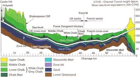
1. The Chalk Marl Horizon
Over the two decades before construction began, engineers conducted hundreds of marine boreholes and extensive geophysical surveys at a total investigation cost of approximately £80 million in 1987 prices. Those surveys identified a consistent stratum of chalk marl, a calcium carbonate and clay composite formally designated the West Melbury Marly Chalk Formation, occupying the lower third of the chalk sequence. The material was soft enough for TBM disc cutters to penetrate efficiently, structurally coherent enough to remain stable without immediate support, and sufficiently low in permeability to protect against the hydrostatic pressures at depth. Rock quality designation values tested consistently around 90 per cent.
On the French side, the chalk marl proved weaker and more fissured than its British counterpart. That single geological asymmetry drove the selection of entirely different TBM types for each national drive, determined advance-rate targets, and shaped the spoil-disposal strategy on both sides of the median line. It is the foundational fact behind every subsequent Channel Tunnel engineering design decision and the starting point for how the Channel Tunnel was built under the English Channel: by finding the one stable enough to bore through its full width.
Breakthrough 2: Three-Tunnel Configuration and the Service Tunnel Strategy
The decision to build three tunnels rather than two is the single most consequential structural choice made in the Eurotunnel construction programme. It added cost and construction time but resolved a set of engineering problems that two rail tunnels alone could not address. Eurotunnel construction records confirm that the service tunnel was driven ahead of the main rail bores, providing contractors with a continuous subsea access route and allowing them to verify actual ground conditions before committing the main TBMs to their full drives.
2. Why Three Tunnels?
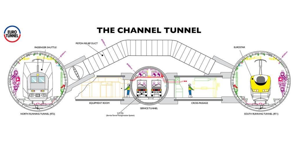
The two rail tunnels, with an internal diameter of 7.6 metres, run parallel to each other at a centreline spacing of 30 metres. The 4.8-metre service tunnel sits between them. Cross-passages link the rail tunnels to the service tunnel at 375-metre intervals; piston relief ducts connect the two rail tunnels directly at 250-metre spacing.
The service tunnel served four functions simultaneously: an excavation pilot, a ventilation backbone maintained at positive pressure, an emergency evacuation route, and a fixed equipment carrier for power cables, drainage lines, and telecommunications infrastructure. The 1996 fire, when an HGV shuttle ignited 19 kilometres from the French portal, validated the design directly. All 34 people trapped in the smoke-filled running tunnel escaped through cross-passages into the pressurised service tunnel and reached safety.
The Institution of Civil Engineers records that cross-passage doors were specified to be operable by a single person without tools, a detail that proved critical under fire conditions. This safety architecture has since influenced the Brenner Base Tunnel, where a similar pilot and safety tunnel forms the spine of the Alpine crossing currently under construction between Italy and Austria.
Further Reading: Brenner Base Tunnel: 9 Extraordinary Engineering Achievements Powering Europe’s Deepest Alpine Crossing
Breakthrough 3: Dual TBM Programmes and Differential Geology
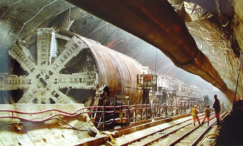
Eleven tunnel boring machines drove the longest undersea rail tunnel that the UK and France have ever produced. No two were identical, because the geology on either side of the median line demanded fundamentally different machine configurations. Understanding the Channel Tunnel boring machine selection requires understanding that differential geology, not contractor preference, dictated every machine specification.
3. Open-Face vs. Earth-Pressure Balance Machines
The British chalk marl was dry and consistent, requiring minimal face support. Contractors deployed open-face TBMs on the UK side, capable of advance rates exceeding 150 metres per week. The French chalk was wetter and more faulted; Transmanche-Link deployed earth-pressure-balance TBMs on the French drives, closed-face machines that maintain positive pressure at the cutting head to counteract groundwater. The asymmetry meant that British TBMs excavated the majority of the tunnel length, despite both national programmes starting simultaneously.
The Channel Tunnel boring machine construction method on the UK side set world-leading records for chalk tunnelling at the time, which reinforced the case for the longest undersea rail tunnel being driven from Britain outward rather than the other way around. The Eurotunnel construction programme generated approximately 8 million cubic metres of excavated chalk. On the British side, that material was used to build the Samphire Hoe nature reserve at the foot of Shakespeare Cliffs, extending the UK coastline by 90 acres. The French operation pumped its chalk slurry behind a 37-metre-high dam.
Each TBM installed precast concrete lining rings as it advanced, each comprising six segments plus a keystone bolted with high-performance gaskets rated for sustained hydrostatic pressure. The lining system was specified for a Channel Tunnel engineering design life of 120 years. One British-side TBM was deliberately buried beneath the Channel at the end of its drive rather than recovered; removing it would have required breaking the completed lining.
Breakthrough 4: Survey Precision and the 1990 Breakthrough
Among all Channel Tunnel engineering challenges, cost, and specifications, the survey problem was the one that money alone could not solve. Two national TBM programmes, driven from opposite coasts through 37.9 kilometres of seabed where GPS signals do not penetrate, had to meet at the median line with an alignment error small enough to allow continuous rail track installation. There was no way to close the survey loop during excavation.
Laser Guidance and Earth Curvature Corrections
Survey teams used laser systems to keep each TBM on course, setting benchmarks along the tunnel walls at sub-millimetre accuracy. Any measurement error is propagated forward without correction. Engineers also had to account for variables absent from surface surveys: the curvature of the Earth across a 38-kilometre baseline, tidal fluctuations that altered instrument readings, and gravitational effects on precise geodetic measurements. The service tunnel breakthrough came in October 1990 when a French probe and a British TBM met beneath the Channel. The alignment error across 37 kilometres of seabed: 358 millimetres horizontally and 58 millimetres vertically. That is less than the width of a standard doorway after boring the equivalent distance from London to Cambridge underground.
Breakthrough 5: Piston Relief Ducts and Aerodynamic Management
A train travelling at 160 kilometres per hour through a sealed 7.6-metre bore generates a pressure wave ahead of it and a partial vacuum behind it. In a Channel Tunnel operating at full capacity with multiple trains in both rail tunnels simultaneously, this creates a complex dynamic pressure environment that affects passenger comfort, structural loads on the lining, and ventilation performance.
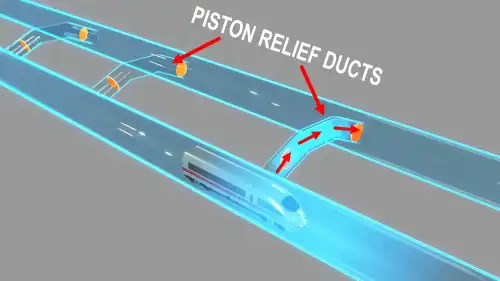
Managing the Piston Effect
Piston relief ducts at 250-metre intervals allow the compressed air column ahead of each train to bleed across into the adjacent tunnel rather than riding ahead of the locomotive across the full 50-kilometre length. This reduces aerodynamic drag on trains, controls pressure fluctuations in passenger coaches, and prevents the tunnel from acting as a resonant pipe. The ventilation strategy uses the service tunnel as a pressurised supply duct: fresh air is discharged via cross-passages along the full length, with stale air exhausting at portals. The England-France undersea tunnel ventilation system can operate bidirectionally in fire conditions, with UK fans blowing and French fans extracting simultaneously, or vice versa, depending on the incident location.
Breakthrough 6: Crossover Caverns and Operational Flexibility
Two crossover caverns sit beneath the Channel, one close to each coast. They are among the largest underground chambers excavated in chalk marl, and they exist specifically to give the England-France undersea tunnel the directional flexibility a purely bidirectional system would lack. Without them, any maintenance or emergency closure of a single section would require shutting the entire tunnel in one direction.
Excavating the Crossover Chambers
Each chamber is approximately 150 metres long, 21 metres wide, and 15 metres high, making them among the largest unsupported chalk marl spans ever constructed. The TBMs bored through each chamber void and then re-entered the chalk to continue their drives. Ground conditions at chamber locations required precise ahead-of-face grouting to control water ingress before excavation.
The Channel Tunnel cross-border crossover design divides each rail tunnel into three operational intervals, allowing any one interval to be isolated for maintenance or emergency response while the remaining five intervals stay in service. That operational segmentation was critical during the 1996 fire and has been used repeatedly for planned maintenance without full tunnel closure.
Breakthrough 7: Tunnel Lining Design for 120-Year Service Life
Every lining ring in the Channel Tunnel was engineered to perform for 120 years under conditions that destroy conventional concrete: sustained hydrostatic pressure from 75 metres of seawater overhead, corrosive saline groundwater in the chalk, dynamic loads from trains at six-minute headways at 160 km/h, and thermal cycling from train-generated heat. The Eurotunnel construction specification required achieving that durability at industrial production rates since TBMs needed a continuous segment supply to maintain advances.
Dual Lining Systems
Two systems were deployed. Through consistent chalk marl, precast reinforced concrete rings provided the primary lining. Cast iron segments, bolted with high-performance gaskets, were reserved for zones of structural instability, particularly on the French side, where the chalk was more faulted and water pressures were higher.
Each ring was positioned by a ring erector arm integrated into the TBM backup train, then used immediately as the reaction point for the hydraulic rams driving the cutting head forward. This bore-erect-advance cycle, repeated across 77 kilometres of total tunnel drive, is the mechanical core of the Eurotunnel construction facts that structural engineers study today. The 750,000 individual lining segments installed are sufficient to face more than 100 large office buildings.
Breakthrough 8: Cross-Border Governance and the IGC Oversight Structure
The Channel Tunnel required two governments to agree on a legal framework, two national railway networks to integrate their signalling protocols, and a single private consortium to manage contractors from both countries simultaneously. The governance structure that emerged was unprecedented in European infrastructure, and its complexity contributed directly to the project’s cost overrun.
The Treaty of Canterbury and Its Cost Consequences
The Treaty of Canterbury, signed by Thatcher and Mitterrand on 12 February 1986, established the legal basis for the Channel Tunnel and created the Intergovernmental Commission (IGC) to oversee construction and operation on behalf of both governments. The IGC exercised broad powers to mandate design and specification changes during construction, particularly on safety, security, and environmental protection. Each mandated change added cost that the original tender estimate did not carry.
The consequences were severe. Initial estimates placed the project at £4.65 billion in 1985 prices; the outturn cost was £9.5 billion, an 80 per cent overrun. Financing costs alone ran 140 per cent above forecast. Eurotunnel suspended debt repayment in September 1995 and required full financial restructuring in 1998. The concession was extended by 34 years, to 2086, in exchange for debt relief. The Channel Tunnel’s engineering challenges, cost overruns, and specification overruns are now standard references in the infrastructure finance literature on optimism bias.
The experience confirms that Channel Tunnel engineering challenges of a technical nature are manageable; governance and commercial challenges, when underdefined at contract, are not. The Channel Tunnel engineering design process confirms that binational regulatory oversight must have a defined scope and change-control procedures from the outset.
Breakthrough 9: Private Finance Structure at Unprecedented Scale
No government funding supported the construction of the Channel Tunnel. How was the Channel Tunnel built through entirely private capital? It assembled the largest private infrastructure finance structure attempted to date: equity from institutional and retail investors across Europe, combined with a syndicated bank loan arranged through a consortium of international lenders. At financial close in 1987, the project mobilised financing from more than 200 banks globally.
Equity, Debt, and the Limits of Optimism
Eurotunnel raised initial equity of £45 million, increased by a £206 million private placement, then conducted a public share offer across the UK and France, raising £770 million. A syndicated bank loan and letter of credit facility arranged a further £5 billion. How was the Channel Tunnel built across two national borders without public money? Through a channel tunnel cross-border concession framework that assigned all construction risk to private equity holders and bank creditors, with no sovereign backstop. Channel Tunnel boring machine construction costs were the only contract element fixed at tender; every other line, including systems, fit-out, and safety upgrades mandated by the IGC, remained open.
The structural weakness was the revenue forecast. Traffic projections systematically overestimated the Channel Tunnel’s share of cross-Channel travel, failing to account for the competitive response of ferry operators, who cut prices and upgraded vessels directly in response to the tunnel’s opening. In its first full year of operation, Eurotunnel reported a loss of £925 million. This pattern appears across other large European sea-crossing projects: the Fehmarnbelt Fixed Link between Denmark and Germany required sustained political commitment to its revenue case over decades of planning and legal challenges.
The Eurotunnel construction financing model has become a textbook case in two directions: it demonstrated that a major cross-border transport link could be delivered without public subsidy, and it proved that demand optimism at the time of the bid could produce a project that performs well operationally for decades while nearly destroying its investors in the first ten years. The American Society of Civil Engineers designated the Channel Tunnel one of the Seven Wonders of the Modern World in 1994, citing the scale and precision of the engineering. The financial system that built it took another decade to stabilise.
Further Reading: Fehmarnbelt Tunnel: 7 Proven Reasons This $11BN Mega-Link Will Transform Scandinavia
Breakthrough 10: Operational Performance and Long-Term Infrastructure Yield
Measuring the Channel Tunnel solely by its construction cost misreads its strategic significance. Over three decades, it has delivered a transport asset whose utilisation and economic contribution have grown well beyond the forecasts that justified the original investment. The case for the longest undersea rail tunnel, the UK-France, was not proven at its opening in 1994; it has been proven by three decades of combined use.
Traffic, Trade, and the ElecLink Energy Interconnector
Since opening in May 1994, the Channel Tunnel has carried more than 537 million passengers and over 109 million vehicles, according to Getlink’s 30th anniversary figures. The concession holder, Getlink SE, reports that the tunnel carries roughly a quarter of all UK-Europe trade. The New Civil Engineer reported in May 2024 that the infrastructure director put the current annual trade figure at £140 billion, with 1.5 million trucks and 2.5 million cars crossing at peak.
Getlink has diversified the tunnel’s revenue base beyond transport. The ElecLink interconnector, installed within the tunnel structure, transmits up to 1 GW of electricity between the French and UK grids, creating a revenue stream entirely independent of passenger and freight volumes. It repositions the Channel Tunnel as an energy infrastructure asset as well as a transport one, a framing now being applied to other long-lifespan civil assets globally. The Seikan Tunnel in Japan similarly demonstrated that the strategic value of a sea crossing compounds over time as the surrounding transport network matures. What was built beneath the English Channel between 1988 and 1994 carries more consequence in 2026 than the original traffic models ever projected.
Channel Tunnel: Construction Challenges and Engineering Responses
The table below summarises the principal technical and commercial challenges encountered during construction, alongside the engineering decisions made in response.
| Challenge | Engineering Response | Outcome |
| Variable French chalk geology | Earth pressure balance TBMs on French drives | Water ingress controlled; slower advance rates accepted |
| Survey accuracy over 38 km of seabed | Laser guidance with Earth curvature and tidal corrections | Alignment error: 358 mm horizontal, 58 mm vertical |
| Subsea fire and evacuation | Pressurised service tunnel; cross-passages every 375 m | All 34 people evacuated safely in the 1996 fire |
| Train-generated pressure waves | Piston relief ducts at 250 m intervals between rail tunnels | Aerodynamic drag controlled; no structural resonance |
| 120-year lining durability | Dual lining: precast concrete rings and cast iron in high-stress zones | Lining rated to resist sustained hydrostatic and dynamic loads |
| 8 million m³ spoil disposal | UK: Samphire Hoe nature reserve. France: hydraulic pumping behind a dam | Coastal landform created; no marine disposal |
| 80% cost overrun on private finance | Debt restructuring, 1998; concession extended to 2086 | The project survived; Getlink returned to profitability |
Technical Block: Channel Tunnel Specifications and Safety Data
Engineers assessing the Channel Tunnel engineering design against other England-France undersea tunnel proposals should use the following as the verified baseline. Every specification listed was governed by the 1987 Concession Agreement and subject to continuous IGC review across both national jurisdictions.
Tunnel Geometry
Three parallel bores: two 7.6-metre internal diameter rail tunnels at 30-metre centreline spacing, and one 4.8-metre service tunnel between them. Channel Tunnel length, depth, and construction engineering facts set the global benchmark for subsea rail design. The total system length is 50.45 kilometres; the Channel Tunnel’s undersea section is 37.9 kilometres, making it the longest undersea rail tunnel by continuous underwater length.
The Seikan Tunnel in Japan is longer overall at 53.85 kilometres but has a shorter underwater section at 23.3 kilometres; the ‘longest undersea rail tunnel UK-France’ designation refers precisely to this 37.9-kilometre sub-seabed bore. The Channel Tunnel’s length, portal-to-portal, is 50.45 kilometres. Maximum depth: 75 metres below the seabed, equivalent to 115 metres below sea level. The cross-border alignment was achieved with an error of only 358 millimetres horizontally across the full 37.9-kilometre drive.
TBM Performance and Excavation
The Channel Tunnel boring machine programme deployed eleven machines across twelve working faces. The Channel Tunnel boring machine construction method differed fundamentally between drives: open-face TBMs on the UK side achieved advance rates exceeding 150 metres per week through competent chalk marl, earth-pressure balance TBMs on the French side advanced more slowly through wetter, more faulted ground.
The Channel Tunnel boring machine fleet generated 8 million cubic metres of excavated material in total. The boring machine construction scheduling required all 11 machines to sequence their drives to maintain continuous ventilation and spoil removal access; the service tunnel breakthrough was achieved in October 1990, and full rail tunnel connections followed in 1991. How was the Channel Tunnel built to such precision underground? By running laser-guided survey benchmarks at sub-millimetre intervals along every tunnel wall, corrected for Earth curvature and tidal variation, from the moment each TBM left its launch chamber.
Safety Infrastructure
Cross-passages at 375-metre intervals (3.3 m diameter). Piston relief ducts at 250-metre intervals (2 m diameter). Service tunnel held at positive pressure throughout operation. Two crossover caverns, each approximately 150 m × 21 m × 15 m. The Channel Tunnel cross-border safety regime is administered by the Channel Tunnel Safety Authority (CTSA), the first binational safety body of its type in European infrastructure, operating continuously across both national jurisdictions. Channel Tunnel cross-border infrastructure engineering safety facts are verified by the 1996 fire investigation report and subsequent CTSA analysis.
The Channel Tunnel engineering challenges in safety governance were substantial: designing a regulatory body that could enforce safety standards across two legal jurisdictions with different national codes, without becoming a vehicle for unlimited cost addition, was as difficult as the engineering itself. The framework has since informed the safety architecture of the Europe mega-tunnels cluster, including the Fehmarnbelt and Brenner Base Tunnel projects.
Conclusion: What the Channel Tunnel Proves
The Channel’s 80 per cent cost overrun, the 140 per cent increase in financing costs, and the 1998 debt restructuring were consequences of a governance framework that allowed a regulatory body to make major specification changes after contracts had been signed. That lesson remains relevant for modern megaprojects, including the Strait of Messina Bridge, because technical ambition must be supported by strong commercial and contractual discipline.
The Channel Tunnel ultimately proved that its engineering approach was sound. Since opening, it has carried more than 537 million passengers and has accounted for a significant share of UK-Europe trade, confirming the long-term value of the project. Its construction methods, particularly the geology-driven use of dual open-face and EPB tunnel boring machines, became a reference point for subsequent major subsea rail tunnels.
The Channel Tunnel construction record remains one of the strongest benchmarks for the delivery of undersea-bored tunnels. The 37.9-kilometre chalk marl bore, driven from opposite coasts and completed with only a 358-millimetre alignment error, demonstrated the precision required for complex subsea infrastructure. For future sea-crossing projects, the Channel Tunnel provides one of the most complete lessons in designing, building, and operating tunnels across their full lifecycle.
Explore More Record-Breaking Tunnel Engineering Projects
From the deepest undersea crossings to the longest subsea road links, the world’s most ambitious tunnel megaprojects reveal how engineers are overcoming extreme geology, pressure, and distance. Discover on Construction Frontier: Global Mega Projects the innovations, construction methods, and engineering breakthroughs shaping the future of underground infrastructure.