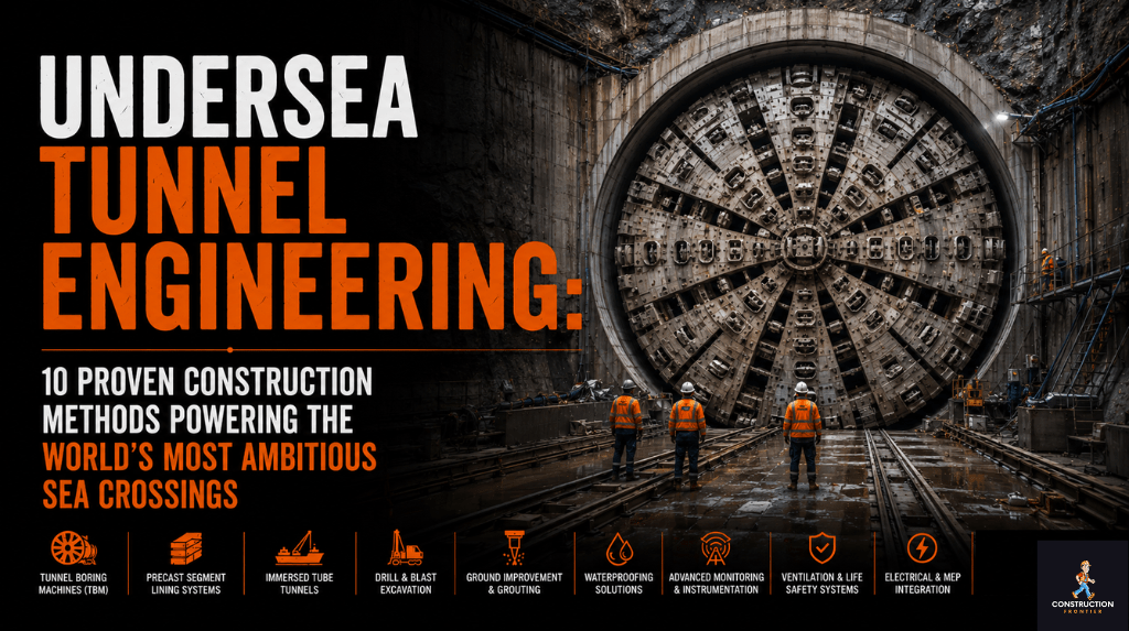
Undersea Tunnel Engineering: 10 Proven Construction Methods Powering the World’s Most Ambitious Sea Crossings
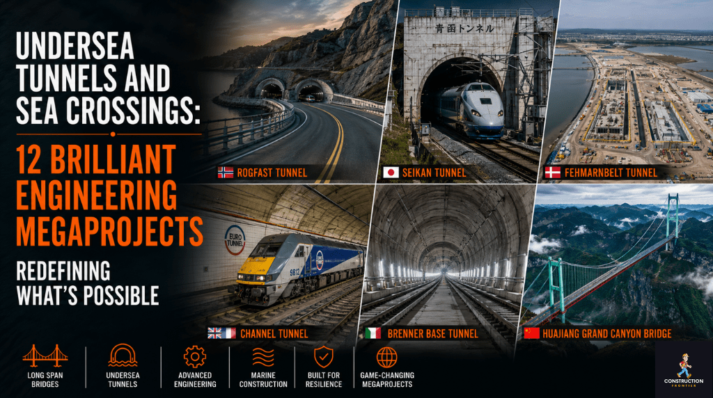
Undersea tunnel engineering is one of civil engineering’s most technically demanding disciplines, combining geological precision, structural design, and materials science under conditions of extreme hydrostatic pressure. From Japan’s Seikan Tunnel, drilled 240 metres below sea level, to Denmark’s Fehmarnbelt immersed tube, the world’s longest sea-crossing tunnels demonstrate that no strait, fjord, or seabed geology is unconquerable. Ten core subsea tunnel construction methods define how engineers select, execute, and deliver these projects across varying depths, ground conditions, and crossing lengths.
Technical Snapshot: Core Undersea Tunnel Construction Methods
| Primary Construction Methods | TBM bored tunnelling, immersed tube, drill-and-blast, cut-and-cover, submerged floating |
| Deepest Operational Undersea Tunnel | Seikan Tunnel, Japan: 240m below sea level |
| Longest Undersea Portion | Channel Tunnel: 37.9km beneath the English Channel |
| Longest Subsea Road Tunnel (under construction) | Rogfast, Norway: 26.7km, 390m depth (opening 2033) |
| Record Immersed Tube Project | Fehmarnbelt Tunnel: 18km, 89 tunnel elements, opening 2029 |
| Typical Groundwater Pressure (Deep Bored) | Up to 2.4 MPa (Seikan Tunnel) |
| Typical TBM Diameter Range | 6m to 17.6m for major sea crossings |
| Primary Waterproofing Approach | Grouting, segmental concrete lining, GINA gaskets, Omega seals |
Each method within undersea tunnel engineering carries specific risk profiles, cost drivers, and geological prerequisites. Understanding how undersea tunnel engineering works step by step, from site investigation through excavation to permanent waterproofing, separates competent execution from costly programme failure on the world’s most ambitious sea crossings.
Introduction: Why Undersea Tunnel Engineering Demands a Different Playbook
No two sea crossings present the same engineering problem. Undersea tunnel engineering is defined by the intersection of variable seabed geology, hydraulic load, corrosion exposure, and the structural consequences of getting any one of those factors wrong. A bridge can be inspected visually and repaired incrementally. A tunnel beneath thirty metres of seawater cannot be patched from the outside; every decision made during undersea tunnel design and build is embedded permanently in the structure.
That constraint pushes engineers toward rigorous site characterisation before a single machine enters the ground. Geotechnical surveys, marine seismic profiling, seabed sampling, and in-situ stress testing are not optional preliminaries; they determine whether the crossing is viable by TBM, by immersed tube, by drill-and-blast, or by a hybrid of subsea tunnel construction methods. How undersea tunnel engineering and sea crossing work step by step begins long before excavation: it starts with data, moves through analytical modelling, and only then proceeds to construction. Undersea tunnel engineering construction methods and challenges are inseparable from the geology that governs them.
The consequence of method misselection is severe. The Seikan Tunnel project, covered in detail in our analysis, endured multiple flood incidents during construction because the fractured Tsugaru Strait geology demanded grouting and drainage strategies that evolved iteratively over years of active tunnelling. The cost of that learning was measured in both time and lives.
This article sets out the ten proven construction methods that define contemporary undersea tunnel engineering, exploring how each is selected, how it is executed at depth and under pressure, and where the discipline is heading as the industry pushes toward longer, deeper, and more complex sea crossings. Proven undersea tunnel engineering methods for long sea crossings do not emerge by accident; they are the product of decades of iterative technical development and post-construction forensic learning.
Table 1: The World’s Major Operational Undersea Tunnels
| Tunnel | Country | Total Length | Subsea Section | Max Depth (m) | Method | Opened |
| Seikan | Japan | 53.85km | 23.3km | 240 | Drill-and-blast | 1988 |
| Channel Tunnel | UK / France | 50.5km | 37.9km | 75 | TBM (slurry) | 1994 |
| Ryfylke | Norway | 14.4km | 14.4km | 292 | Drill-and-blast | 2019 |
| Eiksund | Norway | 7.77km | 7.77km | 287 | Drill-and-blast | 2008 |
| Busan-Geoje | South Korea | 8.2km | 3.7km | 48 | Immersed tube | 2010 |
| Hong Kong-Zhuhai-Macau (subsea) | China | 6.7km | 5.66km | 44 | Immersed tube | 2018 |
| Eysturoy | Faroe Islands | 11.2km | ~9km | 187 | Drill-and-blast | 2020 |
Method 1: Slurry-Shield TBM Boring
For undersea tunnel engineering through soft, saturated, or mixed-face ground (the conditions found beneath most major sea straits), the slurry-shield tunnel boring machine is the dominant tool. The machine maintains face stability by pressurising the excavation chamber with bentonite slurry at a pressure calibrated to counteract the groundwater head acting against the tunnel face. Excavated material mixes with slurry and is pumped to a surface separation plant, where solids are extracted, and slurry is reconditioned for recirculation. This is bored tunnel undersea infrastructure at its most sophisticated.
1.1 How the Slurry Shield Functions Under Pressure
The critical design challenge for slurry TBMs in undersea tunnel engineering is maintaining support pressure within a narrow band: too low and the face collapses; too high and ground heave threatens overlying seabed integrity. Mixshield technology, developed by Herrenknecht, addresses this through a submerged internal wall and an automatically controlled air cushion that decouples slurry circuit pressure from face support pressure. The result is stable face support in heterogeneous geology and under water pressures reaching 10 bars. How engineers overcome pressure and depth in undersea tunnel construction begins at this interface between machine design and ground behaviour.
The world’s largest slurry TBM operates on the Tuen Mun-Chek Lap Kok Link project in Hong Kong, at 17.6 metres in diameter, boring beneath the South China Sea. That diameter is not incidental: it reflects the demand for multi-lane or multi-track undersea infrastructure where a single bore must carry the full structural and operational load of a major transport corridor. The most advanced undersea tunnel engineering techniques in the world are concentrated in these large-diameter slurry drives through challenging marine geology.
1.2 Segment Lining Installation
As the TBM advances, a segment erector installs precast reinforced concrete ring segments behind the cutterhead shield. For undersea tunnel engineering, these segments are manufactured to tight tolerances (typically ±1mm on joint faces) and fitted with EPDM rubber gaskets that compress under ring closure to form the primary watertight seal. Tail-shield void grouting fills the annular gap between the lining extrados and the excavated profile immediately, preventing ground relaxation and water ingress into the tunnel.
The Channel Tunnel deployed eleven TBMs, five from the French side and six from the British side, boring through chalk marl beneath the English Channel at an average depth of 40 metres below the seabed. Chalk marl was selected as the target stratum precisely because its low permeability and structural consistency suited TBM advance without the face instability risks present in sand or fractured rock. The Channel Tunnel remains the benchmark against which all subsequent bored undersea tunnel infrastructure is measured.
Method 2: EPB (Earth Pressure Balance) TBM Boring
Where ground conditions produce cohesive soils (stiff clays, silts, and mixed-face geology at moderate depths), earth-pressure-balance TBMs offer a cost-effective alternative to slurry machines in undersea tunnel engineering. The excavation chamber fills with conditioned spoil (foam, bentonite, and polymer additives injected at the cutterhead) that develops a plastic consistency. A screw conveyor controls the spoil removal rate to maintain chamber pressure, regulated to equal or slightly exceed groundwater pressure at the face. How engineers overcome pressure and depth in undersea tunnel construction with EPB machines depends entirely on soil conditioning: the conditioned spoil must maintain plasticity under the full groundwater head acting at the working depth.
2.1 EPB Versus Slurry: The Selection Logic
The choice between EPB and slurry in bored tunnel undersea infrastructure involves undersea tunnel engineering cost design and geological challenges that go well beyond face stability. Soil gradation and permeability drive the primary decision. EPB performs well in cohesive soils with fine content above 30% and permeability below 1×10⁻⁴ m/s. Below those thresholds, in coarse sands, gravels, or highly fractured rock with high groundwater inflow, slurry shield machines maintain face stability more reliably. For crossings where geology varies along the alignment, Herrenknecht’s Variable Density TBM can switch between EPB and slurry modes without surface intervention, representing one of the most advanced undersea tunnel engineering techniques in the world for variable ground conditions.
The Eysturoy Tunnel in the Faroe Islands, with the world’s first undersea roundabout, used drill-and-blast rather than TBM, a decision driven by the hard basalt geology of the Faroese seabed. As detailed in our coverage on the tunnel’s construction, the competent rock eliminated the instability risks that make TBMs necessary in softer ground, while the relatively short crossing length made the capital cost of a TBM unwarranted. Undersea tunnel engineering cost, design, and geological challenges always intersect at method selection.
Further Reading: Eysturoy Tunnel: The Bold Engineering Breakthrough Behind the World’s First Undersea Roundabout
Table 3: TBM Face Support Method Selection Criteria
| Parameter | Slurry Shield TBM | EPB TBM | Drill-and-Blast |
| Optimal soil type | Coarse sands, gravels, mixed face | Cohesive clays, silts, fine sands | Hard rock (granite, basalt, gneiss) |
| Finess content | >20% problematic for slurry sep. | >30% optimal | N/A (rock) |
| Permeability threshold | Up to 10-3 m/s | Below 10-4 m/s | Managed via pre-grouting |
| Max working pressure | Up to 10 bar (Mixshield) | Up to 6 bar | Governed by grout curtain |
| Spoil removal | Bentonite slurry circuit + separation plant | Screw conveyor + belt conveyor | Muck trucks / rail haulage |
| Face support mechanism | Pressurised bentonite slurry | Conditioned excavated soil | Rock mass self-support + shotcrete |
| Typical TBM diameter (sea crossings) | 8m – 17.6m | 6m – 14m | N/A |
| Indicative capital cost premium | High (slurry plant, separation) | Medium | Low-medium (no TBM) |
| Key projects | Channel Tunnel, HK-ZM-Macau link | Istanbul Marmaray, various urban | Seikan, Eysturoy, Rogfast |
2.2 Lining and Waterproofing
EPB bored tunnels in undersea tunnel engineering use identical segmental lining systems to slurry TBMs. The distinction lies in face support mode, not in the structural approach behind the shield. Hydrophilic rubber waterstops, materials that expand on contact with water, supplement the primary EPDM gaskets at segment joints, providing a secondary sealing mechanism that activates automatically if joint compression is insufficient during installation. Subsea tunnel construction methods built on bored undersea tunnel infrastructure all converge on this layered waterproofing logic.
Method 3: Drill-and-Blast in Hard Rock
Drill-and-blast remains the preferred excavation method for undersea tunnel engineering through competent hard rock, granite, basalt, and gneiss, where TBMs offer no particular face stability advantage and where the capital cost and logistical complexity of a large boring machine cannot be justified by project length or alignment geometry. Undersea tunnel engineering construction methods and challenges in hard rock geology are fundamentally different from those in soft ground: the primary risk shifts from face instability to groundwater inrush through fracture networks, and the engineering response shifts from mechanical face support to pre-excavation grouting and systematic drainage.
3.1 Sequential Excavation and Rock Support
For deep-sea tunnel engineering techniques in hard rock, the New Austrian Tunnelling Method (NATM)-influenced sequential excavation method governs drill-and-blast sequencing. Engineers classify the rock mass using RMR (Rock Mass Rating) or Q-system classifications, which drive primary support design: combinations of rock bolts, wire mesh, and sprayed concrete. As rock quality improves, support becomes lighter. Where weak zones, faults, or fracture networks intersect the alignment, pre-excavation grouting consolidates the ground ahead of the face before blasting proceeds. This adaptive approach defines proven undersea tunnel engineering methods for long sea crossings in igneous and metamorphic geology.
The Rogfast Tunnel in Norway, which will become the world’s longest and deepest subsea road tunnel at 26.7km and 390m depth when complete in 2033, is constructed entirely by drill-and-blast through hard Norwegian gneiss and granite. At 390 metres below sea level, hydrostatic pressure approaches 3.9 MPa. The waterproofing and drainage system design at Rogfast represents one of the most demanding challenges in current deep-sea tunnel engineering techniques. Industry coverage of the Rogfast programme details the fully drained lining concept and high-capacity sump pumping strategy adopted for the crossing, requiring a fully drained lining concept with drainage blankets, collection pipes, and high-capacity sump pumping throughout the tunnel’s operational life.
3.2 Pre-Grouting and Drainage
Pre-excavation grouting in hard rock in undersea tunnel engineering seals fracture networks ahead of the face, reducing groundwater inflow to manageable rates. The Seikan Tunnel’s construction reached groundwater pressures of 2.4 MPa in its deepest sections and depended entirely on systematic pre-grouting to allow excavation to proceed safely. Engineers drilled long fan-pattern grout holes ahead of the face, injecting cement and chemical grout to reduce permeability before blasting. Where inflow still exceeded drainage pump capacity, work stopped, and additional grouting cycles were executed before the face advanced.
Drain holes complement grouting by relieving residual pore pressure ahead of the advancing face. The interaction between grout curtain geometry, drain hole spacing, and face advance rate is modelled analytically, using Mohr-Coulomb elasto-plastic ground models, to ensure the grouted zone provides adequate confinement without over-specifying treatment volume and cost. Undersea tunnel engineering costs, design, and geological challenges meet most acutely in this grouting-and-drainage balance: insufficient treatment risks catastrophic inflow; excessive treatment wastes programme time and project budget.
Method 4: Immersed Tube Construction
The immersed tube is the dominant undersea tunnel engineering method for shallow-water crossings at moderate to long lengths, where seabed geology or water depth makes bored tunnelling uneconomical. The method involves fabricating tunnel elements off-site, steel shell or reinforced concrete; floating them to position on a marine vessel; lowering them into a pre-dredged trench; and making watertight connections between adjacent elements before backfilling the trench. Immersed tube tunnel construction has delivered some of the world’s most complex sea crossings, and its economics at crossing lengths between 2km and 20km are unmatched by any bored tunnel approach.
4.1 Element Fabrication and Immersion
Standard immersed tube elements for undersea tunnel design and build range from 100 to 217 metres in length. Steel shell elements are fabricated in a dry dock, waterproofed with an external membrane, fitted with bulkhead end closures, and launched by flooding the dock. Concrete elements are cast in a purpose-built casting basin and launched similarly. Both types are towed to position in a ballasted, near-neutral buoyancy condition and lowered to the prepared trench bed using a specialised immersion vessel that controls four-point suspension with millimetre accuracy, a process that exemplifies how engineers overcome pressure and depth in undersea tunnel construction at the large-element scale.
The Fehmarnbelt Tunnel between Denmark and Germany will become the world’s longest immersed tube tunnel on completion, 18 kilometres beneath the Baltic Sea, comprising 89 prefabricated concrete elements each 217 metres long. Each standard element contains two road tubes and two rail tubes. The first immersion phase began in 2025. Our detailed coverage of the Fehmarnbelt Tunnel examines the factory construction system, the immersion process, and the geotechnical challenges of dredging through seabed materials of mixed till and sand at up to 40 metres depth. Immersed tube tunnel construction at this scale demands a project-specific industrial ecosystem.
Further Reading: Fehmarnbelt Tunnel: 7 Proven Reasons This $11BN Mega-Link Will Transform Scandinavia
Table 4: Immersed Tube Element Specifications: Selected Major Projects
| Project | Element Length (m) | Element Type | No. Elements | Crossing Length | Status |
| Fehmarnbelt, Denmark/Germany | 217 (std) / 79 (special) | Concrete | 89 | 18km | Under construction, 2029 |
| HK-Zhuhai-Macau, China | 180 | Concrete | 33 | 5.66km | Operational 2018 |
| Busan-Geoje, S. Korea | 180 | Concrete | 18 | 3.7km | Operational 2010 |
| Øresund Tunnel, Denmark/Sweden | 175 | Concrete | 20 | 3.51km | Operational 2000 |
| Dalian Bay, China | Varies (curved sections) | Concrete | 18 | 3km (immersed portion) | Operational 2024 |
| Detroit-Windsor, USA/Canada | ~30 | Steel shell | 11 | 1.6km | Operational 1930 |
4.2 Joint Design and Watertight Connections
The critical waterproofing challenge in immersed tube tunnel construction is the element-to-element joint. GINA gaskets, closed-cell rubber seals mounted on the element face, compress under controlled water pressure during immersion to form the primary seal. An Omega seal provides a secondary backup at the joint interior. After element placement and joint compression, water is pumped from the joint space to create a hydrostatic closure force that locks the seal. The joint must then perform throughout the tunnel’s design life, typically 120 years, under settlement, thermal movement, and seismic loading without losing integrity.
The Dalian Bay Tunnel in China, awarded ENR’s Global Project of the Year for 2024, combined 3 km of immersed tube with 1.5 km of cut-and-cover, with 18 reinforced concrete elements including curved sections fabricated to accommodate the bay’s geometry. Curved immersed tube elements represent an advanced fabrication challenge within undersea tunnel design and build: the joint geometry must accommodate angular deflection and torsional loads not present in straight-element tunnels. This project is among the most advanced undersea tunnel engineering techniques in the world for hybrid sea-crossing delivery.
Method 5: Cut-and-Cover Construction
The cut-and-cover method is the simplest approach in undersea tunnel engineering, applicable at the shallow approach sections of sea crossings where water depth is minimal or where the crossing transitions from seabed to land. Two variants exist: bottom-up (excavate, build structure, backfill) and top-down (install side walls, build roof slab, reinstate surface, excavate beneath). Subsea tunnel construction methods at the landward approaches of major sea crossings almost always incorporate cut-and-cover as the connection between the deep section and the surface portal.
5.1 Application in Sea Crossing Portals
For most undersea tunnel engineering projects, cut-and-cover provides the landward approach sections connecting the deep-bored or immersed tube section to the surface portal. The Dalian Bay Tunnel’s 1.5km cut-and-cover component connected the immersed tube section to the land approach, navigating an uneven rock-and-clay seabed mix that made pure immersed tube construction impractical in the shallow nearshore zone. Understanding how undersea tunnel engineering works step by step requires recognising that the method changes as depth and ground conditions change along the same alignment. Undersea tunnel engineering costs, design and geological challenges differ fundamentally between the portal cut-and-cover sections and the deep-bored or immersed sections of the same crossing.
5.2 Structural Design and Waterproofing
Cut-and-cover tunnel structures in undersea tunnel design and build are typically reinforced concrete box sections with external waterproofing membranes applied before backfilling. Diaphragm walls or contiguous bored pile walls provide ground retention during excavation; in saturated ground, ground freezing or dewatering may be required. The roof slab carries an imposed surcharge from backfill, traffic, or, in some cases, a reinstated waterway bed, demanding careful load case assessment for both construction and operational stages. Undersea tunnel engineering costs, design and geological challenges at cut-and-cover sections are dominated by dewatering requirements and the risk of groundwater uplift on the completed structure.
Method 6: Compressed Air Tunnelling
Before pressurised-face TBMs dominated undersea tunnel engineering, compressed air tunnelling was the standard approach for soft-ground sea crossings. The tunnel was pressurised above ambient to counteract groundwater pressure at the working face, allowing miners to excavate manually or with mechanical equipment in a drained environment. Workers entered and exited through airlocks, with decompression schedules managed to prevent decompression sickness. How engineers overcome pressure and depth in undersea tunnel construction historically relied entirely on this physiological approach to face stabilisation.
6.1 Historical Application and Current Relevance
Compressed air tunnelling reached its practical pressure limit at approximately 3.5 bar, corresponding to about 35 metres of water head. Beyond that, physiological exposure limits for workers became unacceptable, and modern pressurised-face TBMs have rendered the method obsolete for primary excavation. The most advanced undersea tunnel engineering techniques in the world still rely on this technique for hyperbaric interventions: accessing the TBM cutterhead to replace disc cutters or roller bits when the machine cannot safely be stopped, and the face depressurised in running ground. These operations require IMCA-certified saturation diving physicians on standby and strict compliance with decompression schedules extending 48 hours or more for a single access.
6.2 Physiological Constraints and Operational Limits
The decompression obligation at high working pressures imposes a hard ceiling on how long personnel can work at the TBM face in compressed air. At 3 bar, a two-hour hyperbaric work period requires an eight-hour decompression. At 3.5 bar, the decompression extends further, and cumulative exposure limits restrict the number of interventions any individual can perform over a working week.
The most advanced deep-sea tunnel engineering techniques have moved decisively away from human-occupied compressed air working as the primary face support mechanism. Deep-sea tunnel engineering techniques continue to evolve in tool-change procedures and hyperbaric medicine protocols, but the discipline remains essential for maintenance intervention in bored tunnel undersea infrastructure, where face depressurisation would cause catastrophic collapse.
Method 7: Ground Freezing
Ground freezing is a specialist technique used in undersea tunnel engineering where conventional grouting cannot provide adequate ground strength or waterproofing, typically in very high permeability materials such as coarse gravels or where ground chemistry renders cement and chemical grouts ineffective. Refrigerant is circulated through freeze pipes installed in a pattern surrounding the excavation zone, cooling the ground progressively until a frozen arch of sufficient thickness and compressive strength forms around the future excavation.
7.1 Cross Passage and Special Structure Construction
In bored tunnel undersea infrastructure, ground freezing is most commonly deployed for cross-passage construction between parallel tunnel tubes. The cross passage must be excavated through ground outside the primary tunnels, saturated ground that cannot be pre-grouted without unacceptable risk to the primary lining. Freezing creates a localised temporary plug that allows cross-passage excavation without groundwater ingress. Freeze-pipe installation is achieved through the primary tunnel lining, and freeze-front development is monitored by thermistor arrays until the designed frozen wall thickness is confirmed. Proven undersea tunnel engineering methods for long sea crossings depend on reliable cross-passage construction, as these structures are critical to emergency evacuation capacity.
7.2 Limitations and Engineering Considerations
Ground freezing is energy-intensive and time-consuming, and the thaw cycle introduces consolidation settlements that must be managed carefully. For undersea tunnel engineering applications, given the temporary nature of the frozen barrier, it requires that the cross passage must be structurally self-supporting before thawing begins, which requires precise sequencing between freezing operations, excavation, and concrete lining installation. Brine-based systems provide more controllable and energy-efficient freezing than liquid nitrogen; both are used depending on time constraints and the specific ground conditions encountered. Undersea tunnel engineering construction methods and challenges in ground-freezing applications centre on maintaining freeze-pipe integrity under the differential pressures acting at depth.
Method 8: Pipe Jacking and Microtunnelling
Pipe jacking and its smaller-diameter variant, microtunnelling, provide a trenchless construction solution for service tunnels, drainage connections, and utility crossings associated with large undersea tunnel engineering projects. A hydraulic jack system installed in a launch shaft pushes a string of precast concrete or steel pipe sections through the ground behind a remotely operated cutting head. Jacking forces are transmitted through the pipe string as each successive pipe is inserted and jacked forward. Subsea tunnel construction methods for secondary infrastructure routinely combine primary TBM or immersed tube drives with pipe-jacking systems for ventilation ducts, drainage sumps, and cable conduits.
8.1 Role in Sea Crossing Infrastructure
For major sea crossings, pipe jacking serves critical ancillary functions. Ventilation ducts, drainage sumps, cable conduits, and emergency egress shafts may all be constructed by jacking rather than by open excavation. The method is particularly suited to undersea tunnel engineering’s secondary infrastructure because it operates from within the completed main tunnel, minimising surface impact and working within the geometry constraints of the existing underground structure. Proven undersea tunnel engineering methods for long sea crossings depend on the reliability of these secondary systems: a failure of the drainage sump in a deep-bored tunnel can put the primary infrastructure out of service for extended periods.
8.2 Lubrication and Friction Control
The primary engineering challenge in long-distance pipe jacking is skin friction, the cumulative resistance acting on the outside of the pipe string as it advances. Bentonite lubrication is injected through ports in the pipe annulus to reduce friction; intermediate jacking stations (IJSs) distribute jacking force along the pipe string to prevent the lead pipes from overstressing under cumulative load. For undersea tunnel engineering applications where jacking runs extend several hundred metres through saturated ground, IJS design and lubrication management are critical. Understanding how undersea tunnel engineering works step by step in these secondary systems requires the same geological rigour applied to the primary tunnel drive.
Method 9: Hybrid Multi-Method Approaches
The reality of most large-scale undersea tunnel engineering projects is that no single construction method delivers the complete crossing. Geological variability across the alignment, differing depth profiles, and the transition from sea crossing to land approach almost always require a hybrid approach, with different subsea tunnel construction methods applied sequentially or in combination across different sections of the same project. Undersea tunnel design and build at the pillar scale is, in practice, always a multi-method engineering exercise.
9.1 Design Logic for Method Combination
Method selection addresses undersea tunnel engineering costs, design and geological challenges following a clear hierarchy. The deepest, longest, and most geologically complex section determines the primary method. Secondary methods handle transition zones, approaches, and ancillary structures. Alignment geometry is adjusted during preliminary design specifically to extend the zone of most competent geology, reducing the length of ground requiring the most expensive treatment. Proven undersea tunnel engineering methods for long sea crossings are almost always hybrid solutions, because no single stratum type extends uniformly beneath the full length of a major strait or fjord.
The Seikan Tunnel combined drill-and-blast as the primary excavation method with an extensive pre-grouting programme, drainage heading construction ahead of the main tube, and a fully waterproofed lining system. It was not a single-method project; it was a geological response strategy that evolved over nineteen years of construction as new conditions emerged. That adaptive approach defines undersea tunnel engineering construction methods and challenges at their most demanding: the method serves the ground, not the other way around.
9.2 Interface Zones: The Highest Risk Locations
In hybrid undersea tunnel engineering projects, the interface between different construction methods represents the highest risk zone on the alignment. Where a bored tunnel meets an immersed tube element, or where a cut-and-cover section transitions to a mined heading, the structural connection and waterproofing continuity must be designed and executed without the quality assurance protocols of either method. These interfaces require purpose-designed connection structures, enhanced inspection regimes, and specific waterproofing details not present elsewhere on the alignment.
The breadth of megaproject types that combine different engineering approaches across a single crossing shows how project teams across Europe, Asia, and the Americas have integrated multiple disciplines, including immersed tube tunnel construction, bored tunnel undersea infrastructure, and hybrid approaches, into coherent delivery strategies that manage interface risk from design through to commissioning.
Table 2: Construction Method Suitability by Project Type
| Method | Ideal Geology | Water Depth Range | Crossing Length | Key Risk |
| Slurry TBM | Soft ground, mixed face, sands | Any (high-pressure capable) | 2km–50km+ | Face instability; slurry separation cost |
| EPB TBM | Cohesive clays, silts | Moderate (<6 bar) | 2km–20km | Soil conditioning failure; over-pressure |
| Drill-and-Blast | Competent hard rock | Any (grouting-dependent) | Any | Groundwater inrush; geological uncertainty |
| Immersed Tube | Any (dredgeable seabed) | Shallow to moderate (≤60m) | 0.5km–20km+ | Joint integrity; dredge spoil disposal |
| Cut-and-Cover | Any (stable excavation) | Very shallow/nearshore only | Approach sections only | Dewatering; groundwater uplift |
| Ground Freezing | Any (cross passages) | N/A (secondary structure) | Short sections only | Thaw settlement; energy cost |
| Submerged Floating | Deep fjords / wide straits | 20m–1,200m+ | 0.5km–5km (concept) | Hydrodynamic resonance; tether fatigue |
Method 10: Submerged Floating Tunnel (Emerging Frontier)
The Submerged Floating Tunnel (SFT), sometimes called an ‘Archimedes Bridge’, represents the most significant emerging concept in undersea tunnel engineering. The principle is straightforward: a tunnel structure with net positive buoyancy is anchored below the water surface, either by tethers to the seabed, by pontoons at the surface, or by a combination of both. Vehicles or trains pass through the tunnel at a controlled depth, typically 20 to 30 metres below the surface, well clear of shipping lanes. No SFT has been built anywhere in the world, but the concept is advancing toward feasibility status in Norway, Italy, and South Korea.
10.1 Engineering Principles and Design Challenges
The SFT solves a specific problem that neither bridges nor conventional tunnels can address economically: fjords and straits that are simultaneously too wide for a cable-stayed bridge, too deep for a conventional bored tunnel, and too exposed for a floating bridge. Norway’s E39 coastal highway faces this problem across several of its deepest fjords, including Sognefjord at 1,200 metres, far beyond the reach of any bored or immersed tube approach. Deep-sea tunnel engineering techniques currently have no answer for crossings of this depth; the SFT is the only viable concept.
The Norwegian Public Roads Administration has proposed SFTs as part of the E39 ferry-free initiative, with construction potentially beginning before 2050 at an estimated programme cost exceeding USD 40 billion. The engineering challenges are formidable: dynamic loading from waves and currents acting on a buoyant structure with no rigid connection to the seabed creates resonance risks absent from conventional undersea tunnel engineering. Tether fatigue, anchor point geology at extreme depths, and the long-term hydrodynamic behaviour of the structure all require physical testing at a scale that has not yet been attempted. Understanding how engineers overcome pressure and depth in undersea tunnel construction with SFTs requires solving hydrodynamic loading problems that have no historical precedent in the industry.
10.2 Regulatory Context and Industry Precedent
No submerged floating tunnel has been built anywhere in the world. The concept has been studied in Norway, Italy, and South Korea since the 1970s, but feasibility studies have not yet produced a funded, consented project. Most advanced undersea tunnel engineering techniques in the world currently exist in the conceptual or experimental validation phase for SFTs. Among the most advanced undersea tunnel engineering techniques in the world, now approaching detailed feasibility, the Norwegian E39 SFT proposals are the furthest advanced in state funding and technical documentation.
The method’s place in the proven construction toolkit remains provisional, contingent on the completion of the first operational structure and confirmation of long-term performance under real environmental loading. Undersea tunnel design and build have always advanced through a small number of landmark projects that established new precedents; the SFT waits for its Seikan or Channel Tunnel moment.
Table 5: Undersea Tunnel Projects Under Construction and in Advanced Planning (2025–2040)
| Project | Location | Length | Method | Depth | Target Opening | Est. Cost |
| Rogfast | Norway | 26.7km | Drill-and-blast | 390m | 2033 | USD 3.2bn |
| Fehmarnbelt | Denmark/Germany | 18km | Immersed tube | 40m | 2029 | EUR 7.4bn |
| Istanbul Strait Rail Crossing | Turkey | ~13.6km | TBM bored | ~85m | 2028 | USD 4.5bn |
| 2nd Qingdao Jiaozhou Bay | China | 15.87km | TBM / immersed | ~55m | TBC | TBC |
| E39 SFT (Sognefjord) | Norway | ~4km | Submerged floating | 300m+ | Post-2040 | USD 25bn+ (corridor) |
Technical Block: How Engineers Overcome Pressure and Depth in Undersea Tunnel Construction
Undersea tunnel engineering demands a highly specialised, risk-mitigated approach to withstand extreme hydrostatic pressures, variable geology, and aggressive marine environments. Constructing permanent transportation links beneath the seabed requires a seamless transition from probabilistic geological modelling to robust structural and environmental engineering. To achieve a 100-plus-year design life, project teams must systematically integrate multi-layered waterproofing defences, heavy-duty structural linings, and active life-safety systems. The following core engineering disciplines outline how modern subsea projects mitigate extreme depth and pressure from initial feasibility through to long-term lifecycle monitoring.
1. Geotechnical Investigation
Every undersea tunnel engineering project begins with a site investigation programme that establishes the subsurface model. Marine seismic reflection surveys map the stratigraphy in three dimensions across the full crossing alignment. Borehole drilling through the seabed collects rock cores and soil samples for laboratory testing. In-situ pressuremeter and permeability tests quantify ground stiffness and hydraulic conductivity.
The resulting ground model, never complete, always probabilistic, drives all subsequent design and risk decisions for the chosen subsea tunnel construction methods. ITA-AITES technical guidelines on site investigation for underwater tunnels set the international standard for ground model completeness thresholds. Undersea tunnel engineering cost, design, and geological challenges cannot be separated: the geology determines the cost. Every undersea tunnel engineering cost, design and geological challenge assessment begins here, in the borehole log and the seismic section.
2. Structural Lining Design
Tunnel lining design for undersea tunnel engineering must account for permanent groundwater pressure, construction-stage loads, seismic loading, and long-term creep and durability under marine conditions. Segmental concrete linings for TBM tunnels are designed to Eurocode 2 or equivalent standards, with durability specifications requiring concrete mix designs that resist sulphate attack, chloride-induced rebar corrosion, and the mechanical stresses of segment handling, installation, and long-term ground loading. Immersed tube sections require specific analysis of flotation forces, thermal expansion, and joint rotation under differential settlement. Undersea tunnel design and build at the lining design stage is where the geotechnical model and the structural model must converge into a consistent set of design loads.
3. Waterproofing Systems
The waterproofing system in proven undersea tunnel engineering methods for long sea crossings operates on a defence-in-depth principle: no single element is relied upon exclusively. For bored tunnels, the hierarchy is segmented concrete impermeability, EPDM gaskets at segment joints, hydrophilic waterstops, and secondary grouted annular void filling. For immersed tube tunnel construction, the hierarchy is the GINA gasket primary seal, the Omega seal secondary backup, joint monitoring instrumentation, and provision for regrouting the joint from inside the tunnel if movement compromises the primary seal. Bored tunnel, undersea infrastructure, and immersed tube systems share the same philosophical approach to waterproofing, despite deploying fundamentally different physical mechanisms.
Table 6: Waterproofing Defence-in-Depth: Bored Tunnel vs Immersed Tube
| Defence Layer | Bored Tunnel (TBM) | Immersed Tube | Function |
| Primary seal | Segment concrete mix impermeability (w/c ≤0.40) | GINA gasket (compressed rubber) | Excludes bulk groundwater |
| Secondary seal | EPDM gaskets at segment joints | Omega seal (clamped interior) | Backup if the primary is compromised |
| Tertiary backup | Hydrophilic waterstops at radial joints | Internal re-grouting provision | Activates on water contact or joint movement |
| Void filling | Tail-shield annular void grouting | Element-to-trench backfill | Prevents ground relaxation/water paths |
| Secondary lining | Cast-in-situ concrete (where specified) | Internal concrete invert and walls | Structural redundancy and service life extension |
| Monitoring | Piezometers, fibre-optic strain sensors | Joint gap sensors, inclinometers | Early warning of changes requiring intervention |
| Design life | 100–120 years (segmental lining) | 100–120 years (GINA 100yr rated) | Full design-life waterproofing continuity |
4. Ventilation Engineering
Road tunnels in undersea tunnel engineering require longitudinal or transverse ventilation systems that extract vehicle emissions and maintain CO and NO₂ concentrations within safe limits. For long tunnels such as Rogfast (26.7 km), ventilation shafts mid-crossing are not feasible beneath 390 m of seawater; the entire ventilation strategy functions from portal-mounted jet fan systems supplemented by the piston effect from traffic flow. Fire ventilation, controlling smoke spread during emergency evacuation, is the critical design case in deep-sea tunnel engineering techniques, determining ventilation capacity, fan redundancy, and escape route spacing throughout the crossing.
5. Structural Health Monitoring
Structural health monitoring systems in operational undersea tunnel engineering infrastructure include fibre-optic strain sensing embedded in lining segments, convergence monitoring arrays, piezometer networks measuring groundwater pressure behind the lining, and corrosion potential monitoring of reinforcing steel. For immersed tube tunnel construction, inclinometers and gap sensors track differential settlement and joint opening throughout the tunnel’s life.
Real-time data feeds inform maintenance decisions and provide early warning of changes in structural behaviour that warrant investigation. Understanding how undersea tunnel engineering works step by step through the operational phase requires data infrastructure as sophisticated as the construction methods that built the tunnel. How undersea tunnel engineering works step by step, from feasibility through to long-term monitoring, is the full cycle that project teams must master.
Further Reading: Revolutionary Smart Sensors in Concrete: 10 Key Metrics They Monitor to Improve Structural Performance
Conclusion: How Method Selection Determines Whether a Sea Crossing Gets Built
Undersea tunnel engineering is not a discipline where aspiration drives outcomes independently of geology. The method used to bore, sink, freeze, or jack a tunnel beneath the sea determines whether the project is financially viable, geologically deliverable, and operationally safe for a century of use. The ten methods examined here, from slurry-shield TBM boring to the emerging submerged floating tunnel concept, each solve a specific combination of geological, hydrological, and logistical constraints.
Undersea tunnel engineering construction methods and challenges are inseparable from site conditions; none of these methods is universally applicable, and all are tools assembled project by project based on evidence rather than precedent. Mapping undersea tunnel engineering construction methods and challenges against a verified geological model is the starting point for every viable sea crossing. The pipeline of projects under development confirms that undersea tunnel engineering will face its most demanding challenges in the next two decades: Rogfast is pushing bored tunnelling to 390m depth through Norwegian rock; the Fehmarnbelt is setting new standards for immersed tube tunnel construction scale and precision; Norway’s SFT proposals are waiting for a political and technical window to advance from concept to consent.
The engineers who deliver these crossings are already making the method selection decisions that will define each project’s outcome. Getting those decisions right, grounded in geology, not aspiration, is what separates successful, proven undersea tunnel engineering methods for long sea crossings from cost overruns, programme failures, and structural incidents that define a project’s legacy for the wrong reasons.
Explore More Tunnel Engineering Breakthroughs
Undersea tunnel engineering continues to push the limits of geology, materials, and construction technology, transforming impossible sea crossings into critical transport links. Explore more at Construction Frontier: Global Mega Projects for insights into the world’s greatest tunnel megaprojects, infrastructure innovations, and engineering solutions shaping global connectivity.