Bridge Engineering at Scale: 7 Proven Systems Powering Megabridges Worldwide
Megabridge engineering combines suspension, cable-stayed, arch, truss, foundation, material, and dynamic control systems to carry live loads across spans exceeding one kilometre and heights beyond 300 metres. Seven structural systems recur across the world’s largest crossings, each solving a distinct problem in bridge load distribution, from the Akashi Kaikyo Bridge’s 1,991-metre central span to the Chenab Bridge’s 467-metre steel arch. Engineers select and combine these systems based on span length, ground conditions, seismic exposure, and wind loading rather than on architectural preference alone, and the choices made at this stage define how a structure performs over the next century.
Technical Snapshot: Core Structural Systems in Megabridge Engineering
| System | Primary Load Path | Typical Span Range | Representative Megabridge | Core Material |
| Suspension | Tension through the main cables into towers and anchorages | 1,000m – 2,000m+ | Akashi Kaikyo Bridge, Japan | High-strength galvanised steel wire |
| Cable-Stayed | Direct tension from deck to mast | 200m – 1,100m | Millau Viaduct, France | Steel deck, reinforced concrete pylons |
| Arch | Compression through the rib into abutments | 150m – 550m | Chenab Bridge, India | Structural steel, blast-resistant grade steel |
| Beam, Truss, Box-Girder | Bending and shear distribution along the span | 30m – 300m | Multi-span viaduct approaches | Orthotropic steel decks, precast concrete |
| Foundation and Substructure | Vertical and lateral load transfer to the ground | N/A | Hong Kong-Zhuhai-Macau Bridge | Caissons, driven piles, immersed tube segments |
| Material Systems | Strength-to-weight and durability optimisation | N/A | Varies by project | UHPC, weathering steel, fibre composites |
| Dynamic Control | Damping of wind, seismic, and traffic loads | N/A | Akashi Kaikyo Bridge (tuned dampers) | Tuned mass dampers, seismic isolators |
These seven systems form the technical backbone of megabridge engineering, and understanding how they interact is what separates a functional crossing from a megabridge capable of carrying decades of traffic across extreme terrain.
Introduction: Megabridge Engineering at Scale
Every megabridge on Earth is an argument between gravity and geometry. The engineer’s task is to move enormous static and live loads, deck weight, vehicles, trains, wind, and seismic forces, from the point where they occur to the ground where they can be safely absorbed. Readers who have explored the breakthrough designs behind the world’s tallest bridges will already recognise that height alone does not make a structure exceptional. What makes a crossing a genuine feat of megabridge engineering is the coordinated use of structural systems that each carry a specific share of the load.
This article breaks megabridge engineering into seven proven systems: suspension, cable-stayed, arch, beam-and-truss, foundation and substructure, material systems, and dynamic control. Each system solves a different structural problem, and most megabridges combine two or more of them within a single crossing. Understanding bridge load distribution at this level explains why certain designs succeed in seismic zones, deep gorges, or typhoon corridors where others would fail. The sections below examine the engineering principles, the materials, and the real-world megabridges that prove each system works at scale.
Megabridge engineering has also become an economic discipline, not only a structural one. A single decision about the structural system can shift construction costs, schedules, and lifetime maintenance liabilities by hundreds of millions of dollars on a major crossing. For investors and policymakers evaluating large-scale bridge engineering proposals, the seven systems covered here provide the technical vocabulary needed to interrogate a design brief rather than simply accept it. Engineering principles of large-scale bridges are, at their core, a set of trade-offs between span length, ground conditions, material cost, and long-term durability, and every megabridge on record reflects a specific answer to that trade-off.

System One: Suspension Systems and the Physics of the Long Span
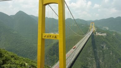
Suspension systems remain the only proven method for crossing spans beyond 1,600 metres without intermediate supports in open water or deep gorges. The system works entirely in tension: two main cables, anchored at each end and draped over paired towers, carry the deck load through vertical hangers. This is one of the clearest structural systems in bridges because every element has a single, dominant stress state: tension in the cables and hangers and compression in the towers, which simplifies analysis even as the absolute scale of the forces involved grows enormous.
Main Cables and Catenary Load Paths
The main cable takes the shape of a catenary curve under uniform load, and its geometry is defined by the sag-to-span ratio, typically between 1:9 and 1:11. A shallower sag increases cable tension and anchorage demand; a deeper sag reduces tension but increases tower height. This ratio is one of the first calculations in any large-scale bridge engineering brief, because it fixes the size of every downstream component, from strand count to anchorage block volume.
Towers, Anchorages, and Vertical Load Transfer
Suspension towers carry almost pure compression, which allows them to be built extremely tall relative to their cross-section, provided the foundation below can resist the resulting overturning moment. Anchorages at each end of the bridge resist the horizontal pull of the main cables and are often the largest single concrete pour on the entire project. Bridge engineers designing for scale must size these anchorages for the full cable tension under maximum load, plus a safety margin for wind and seismic combinations, a calculation that governs anchorage geometry long before deck design begins.
Erection Sequencing for Suspension Decks
Suspension deck erection typically proceeds from the towers outward, with prefabricated deck sections lifted into place and connected to hangers in a carefully sequenced order to keep cable geometry within tolerance throughout construction. Because the main cables are already under load before a single deck section is hung, engineers must model how each new section changes cable sag and tower deflection, a process that makes suspension erection one of the more demanding techniques in megabridge engineering.
Case Study: The Akashi Kaikyo Bridge’s Central Span
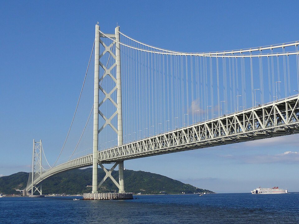
The Akashi Kaikyo Bridge across Japan’s Akashi Strait demonstrates suspension engineering at its most extreme. Its central span measures 1,991 metres between towers that rise roughly 283 metres above the water, and its main cables are each formed from 290 strands of galvanised steel wire. The bridge was designed to withstand winds exceeding 285 kilometres per hour and earthquakes of magnitude 8 or greater, and its central span grew by nearly a metre mid-construction during the 1995 Great Hanshin earthquake, which shifted the still-unfinished towers. Readers researching the mechanics behind this system in more depth will find further detail in the dedicated guide to structural stability in long-span suspension bridge design.
Technical Comparison: Suspension System Sag Ratios and Structural Effect
| Sag-to-Span Ratio | Cable Tension | Tower Height Demand | Typical Application |
| 1:9 (shallower sag) | Higher | Lower | Sites where tower height is constrained |
| 1:10 (mid-range) | Moderate | Moderate | Most modern long-span designs |
| 1:11 (deeper sag) | Lower | Higher | Sites where anchorage capacity is limited |
System Two: Cable-Stayed Systems and Direct Load Transfer
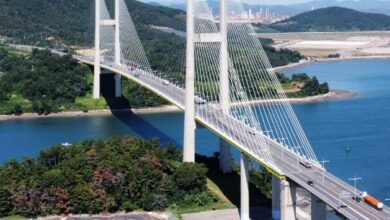
Cable-stayed systems have overtaken suspension bridges as the fastest-growing solution for spans between 200 and 1,100 metres, largely because they require less steel per metre of deck and can be erected without the massive anchorages that suspension bridges demand. Instead of draping over towers, stay cables run in straight lines directly from the mast to the deck, each cable in its own independent tension path, giving engineers finer control over bridge load distribution across the length of the structure.
Stay Cable Geometry and Deck Stiffness
Because each stay cable acts as an elastic support point along the deck, the number and spacing of cables directly determine the deck’s stiffness. Fan, harp, and semi-fan arrangements each distribute load differently across the mast height, and modern designs increasingly favour dense fan arrangements because they reduce individual cable size and simplify replacement during maintenance. This is a core principle of modern bridge construction methods for medium-to-long spans, where geometry, not raw material quantity, is the primary lever for controlling deck depth and weight.
Mast Configuration and Foundation Demand
A cable-stayed mast carries both the vertical load of the stays and a horizontal component that must be balanced by the deck or by back-stay cables anchored beyond the main span. Multi-span cable-stayed structures, where a single deck is supported by a series of masts rather than one central tower, introduce additional complexity because each intermediate mast must resist unbalanced loading when traffic or wind loads one side of the structure more than the other. Foundation demand under each mast can rival that of a suspension tower, despite the shorter overall span, a reminder that cable-stayed engineering rarely scales down as neatly as the drawing suggests.
Cantilever Construction and Cable Stressing
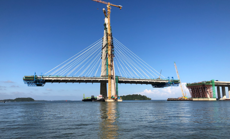
Cable-stayed decks are usually built by balanced cantilever construction, extending the deck symmetrically from each mast while stay cables are stressed in sequence to control deflection. Engineers monitor deck camber continuously during this phase, since even small stressing errors compound across dozens of cable stages. This is one of the more precise megabridge construction techniques explained in structural engineering training, because a single mis-stressed cable can throw an entire span out of tolerance.
Case Study: Millau Viaduct’s Multi-Span Cable Fans
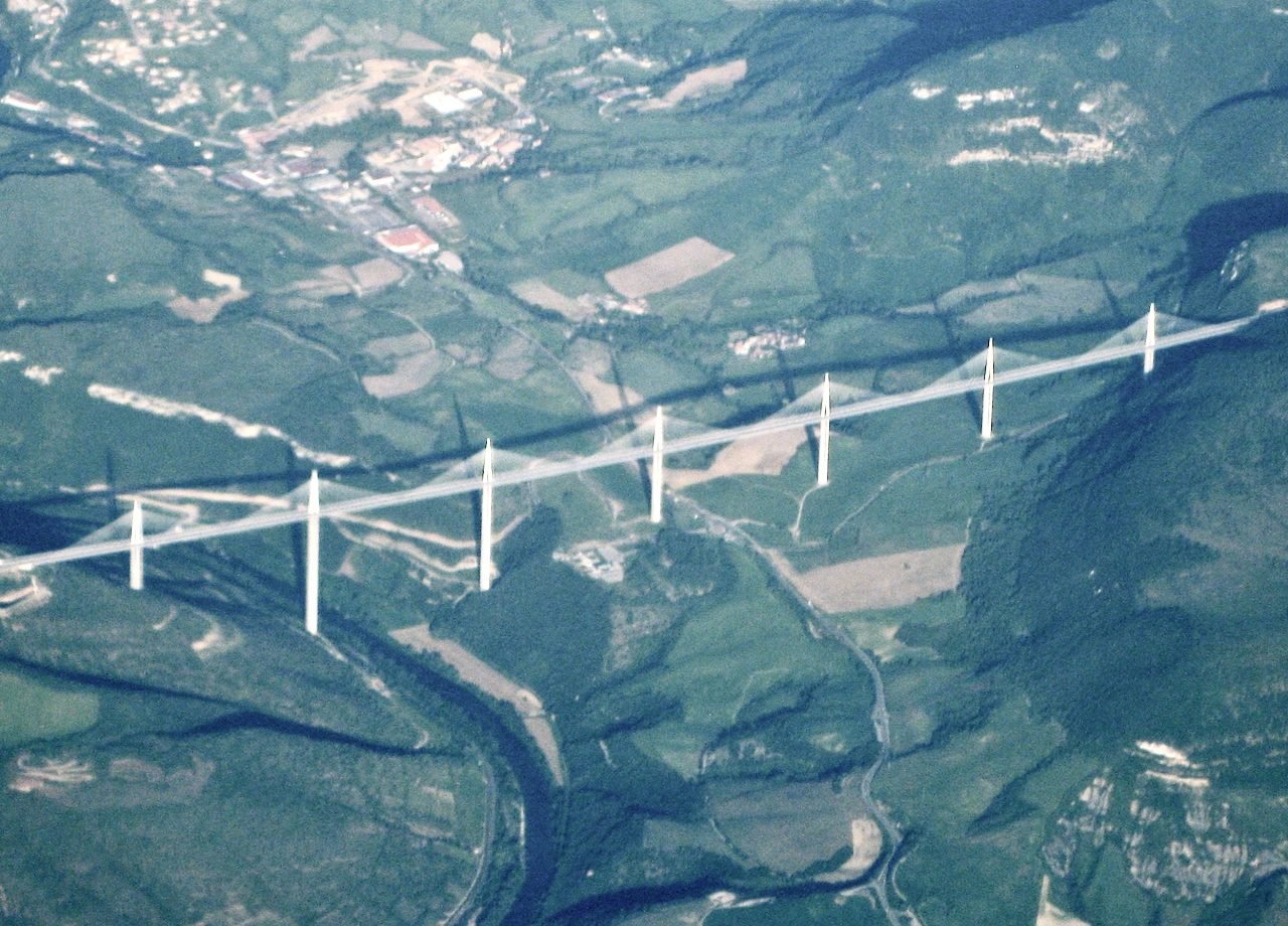
The Millau Viaduct in southern France illustrates how far this structural system can be pushed at scale. Seven concrete piers, the tallest reaching approximately 245 metres, carry seven steel masts standing 87 metres above the deck, each supporting eleven pairs of stay cables. The deck itself, a continuous steel box weighing roughly 36,000 tonnes, was built in two halves and launched horizontally into position using hydraulic jacks, a construction sequence documented in detail in the case for cable-stayed design as the industry’s fastest-growing structural choice. At 343 metres to its highest mast, the viaduct remains one of the tallest structures of any kind ever built for a road crossing.
Further Reading: Cable-Stayed Bridges: 6 Reasons They’re the Fastest-Growing Design
System Three: Arch Systems and Compression-Dominant Design
Arch systems predate both suspension and cable-stayed engineering by centuries, yet they remain the preferred solution wherever a deep, narrow gorge offers strong rock abutments and a rigid deck is required, such as for rail traffic. The arch works in almost pure compression, transferring load outward and downward into the abutments rather than upward into the towers, which is why arch systems remain central to bridge structures in mountainous, rail-heavy corridors.
Thrust, Abutments, and Ground Conditions
An arch generates horizontal thrust at its base, which must be resisted by the surrounding ground or a tied structural member. This is why arch bridges are concentrated in areas with competent rock, since soft or fractured ground cannot withstand the outward thrust without requiring expensive additional foundation work. Arch design, therefore, begins with a geotechnical assessment long before any structural steel is specified, and the results can rule an arch solution in or out before design work advances further. Few structural systems in bridges depend as heavily on site geology as the arch does.
Steel vs Concrete Arch Behaviour
Steel arches allow longer spans and lighter self-weight than concrete equivalents, which matters enormously when every tonne of arch material must be lifted or cantilevered into position above a gorge with no access from below. Concrete arches, by contrast, offer higher mass and inherent damping against traffic-induced vibration, making them common in shorter, high-traffic-volume crossings where long-term maintenance costs matter more than construction-phase logistics.
Technical Comparison: Steel vs Concrete Arch Systems
| Attribute | Steel Arch | Concrete Arch |
| Self-weight | Lower; favours longer spans | Higher; limits the maximum span |
| Achievable span | Up to and beyond 500m | Typically under 300m |
| Damping behaviour | Lower inherent damping | Higher inherent damping |
| Erection method | Cantilever from both banks | Falsework or cast segments |
| Best suited to | Deep gorges, rail loading | Moderate spans, high traffic volume |
Case Study: Chenab Bridge’s Single-Span Steel Arch
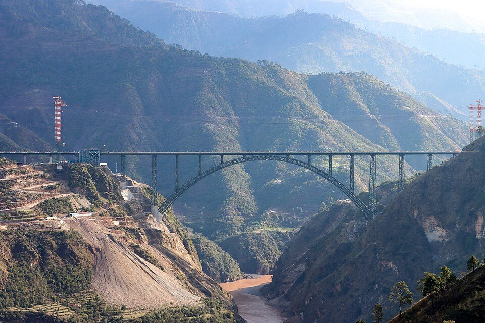
The Chenab Rail Bridge in Jammu and Kashmir carries a single railway track 359 metres above the riverbed on a two-rib steel arch spanning 467 metres, making it the world’s tallest railway arch bridge. Engineers used cantilever erection from both banks, supported by some of the tallest cable cranes ever deployed on a bridge project, to close the arch without falsework reaching the valley floor. The structure was engineered to resist magnitude 8 seismic events and wind speeds above 260 kilometres per hour, confirming that arch systems still outperform cable-supported alternatives where rigidity under heavy, concentrated rail loading is the governing design case.
System Four: Beam, Girder, and Truss Systems for Load Distribution
Not every span in a megabridge crosses open water or a deep gorge. The majority of the total length of most large-scale crossings consists of approach viaducts, where beam, girder, and truss systems carry the deck across shorter, repetitive spans between piers. These systems are the workhorses of modern bridge construction methods precisely because their behaviour is predictable and their fabrication can be standardised across dozens or hundreds of identical spans.
Bending Moments and Shear in Long Viaducts
A simply supported beam develops maximum bending moment at midspan and maximum shear near the supports, a pattern that becomes more complex once spans are made continuous over multiple piers. Continuous multi-span girders redistribute bending moment between spans, reducing the depth of steel or concrete required at midspan. It is a good illustration of how load distribution works in megabridges away from the headline span, where the engineering is repetitive rather than spectacular but no less demanding.
Box Girders and Orthotropic Decks
Steel box girders combine high torsional stiffness with relatively low self-weight, which is why they dominate modern cable-stayed decks and long viaduct approaches alike. Orthotropic steel decks, where a thin steel plate is stiffened by ribs welded beneath it, further cut deck weight compared with concrete slabs, an advantage that compounds across a viaduct several kilometres long. It is a clear illustration of bridge construction materials chosen for their effect on the structural system, not solely for cost.
Segmental and Modular Construction Sequencing
Precast segmental construction, where deck sections are cast off-site and lifted or launched into position, has become standard practice for the beam and girder portions of most megabridges because it removes weather-dependent, labour-intensive fieldwork from the critical path. This approach pairs naturally with the truss and beam systems covered in the dedicated breakdown of the three essential systems behind beam, arch, and truss design, which examines how each system distributes load differently along the span.
Further Reading: Beam, Arch, and Truss Bridges: 3 Essential Systems Powering Design
Comparing Beam, Truss, and Box-Girder Performance
| Configuration | Best Suited To | Self-Weight | Construction Speed |
| Simple Beam | Short, low-traffic crossings | Low to moderate | Fast, minimal fabrication complexity |
| Truss | Rail loading, longer individual spans | Low relative to stiffness | Slower, more connection detailing |
| Steel Box Girder | Long viaducts, cable-stayed decks | Moderate, high torsional stiffness | Fast with segmental methods |
System Five: Foundation and Substructure Systems in Difficult Ground
No structural system above the water line functions without a foundation capable of transferring its load into competent ground, and megabridge foundations frequently represent the single largest cost and schedule risk on the project. Deep water, soft marine sediment, seismic faulting, and shipping clearance requirements all shape how bridge engineers design for scale below the surface, often before the visible structural system above the deck has even been finalised.
Caissons, Piles, and Deep-Water Piers
Large-diameter caissons, sunk and filled with concrete, remain the standard solution for towers founded in open water, while driven or bored piles extend load transfer into deeper bearing strata where surface soils alone cannot carry the vertical load. Pier foundations for a single major tower can require hundreds of piles driven tens of metres below the seabed, particularly in estuarine conditions where the upper soil layers are soft and compressible. Foundation design rarely gets the attention that the more visible structural systems in bridges receive, yet it determines whether everything above the waterline performs as intended.
Immersed Tubes and Hybrid Bridge-Tunnel Systems
Where shipping lanes or airport flight paths make a bridge crossing impractical, engineers switch to immersed tube tunnels rather than continuing the structural system overhead. The Hong Kong-Zhuhai-Macau Bridge demonstrates this hybrid approach at unprecedented scale, combining 22.9 kilometres of viaduct with a 6.7-kilometre immersed-tube tunnel, connected by two artificial islands, allowing large vessels to pass overhead while traffic continues below the seabed. This kind of solution sits at the extreme end of large-scale bridge engineering, and the full range of techniques used where terrain, water depth, or climate push standard foundation methods beyond their limits is covered in four proven approaches to engineering crossings in the world’s most demanding environments.
Seismic and Scour Considerations
Foundations in seismically active or fast-flowing water must also resist lateral forces that static load calculations alone do not capture. Scour, the erosion of riverbed or seabed material around a pier, can undermine even a well-designed foundation over decades, which is why modern megabridge foundations increasingly incorporate scour protection aprons and continuous monitoring instrumentation as standard features rather than optional additions. Foundation design of this kind rarely appears in public renderings, yet it governs whether the visible structure above survives its design life.
Technical Comparison: Foundation Systems by Site Condition
| Foundation Type | Best Suited To | Primary Risk Addressed |
| Large-diameter caisson | Open-water towers on a competent seabed | Overturning moment, wave loading |
| Driven or bored piles | Soft or compressible upper soils | Insufficient bearing capacity near the surface |
| Immersed tube tunnel | Active shipping lanes, flight paths | Navigational and airspace clearance |
| Scour protection apron | Fast-flowing rivers, tidal estuaries | Bed erosion around the pier base |
System Six: Material Systems That Enable Scale
Structural geometry only works if the materials it relies on can deliver the required strength-to-weight ratio, corrosion resistance, and fatigue life across a service life that now routinely exceeds 100 years. Materials used in megabridge construction have advanced substantially over the past three decades, and this shift is as significant to bridge engineering principles as any change in structural form.
High-Strength and Weathering Steel
Modern bridge cables and structural steel members use high-strength galvanised or weathering-grade steel that resists corrosion without the need for constant repainting, reducing lifecycle maintenance costs for structures that are frequently inaccessible for routine work. Weathering steel forms a stable oxide layer that protects the underlying material, a property especially valuable on remote viaducts and river crossings where maintenance access is limited or seasonal.
Ultra-High Performance Concrete and Precast Systems
Ultra-high performance concrete, engineered with steel fibre reinforcement and a dense particle matrix, delivers compressive strength several times that of conventional concrete, along with markedly higher tensile capacity. The Federal Highway Administration’s technical guidance on UHPC deployment confirms that more than 400 bridges across the United States now use the material, mostly for prefabricated element connections and deck preservation, because it allows thinner sections, fewer girders, and faster field-cast joints between precast units. This shift towards factory-controlled materials reflects a broader move in bridge construction materials away from cast-in-place work and towards accelerated, quality-controlled assembly.
Composite and Hybrid Material Combinations
Many megabridges now combine materials within a single structural system, such as steel decks on concrete piers, composite steel-concrete girders, or fibre-reinforced polymer components, in high-corrosion marine environments. This hybrid approach allows engineers to place each material where its properties are most valuable: steel, where tensile strength and reduced weight matter; and concrete, where compressive strength and damping are advantageous, reflecting a mature, deliberate approach to modern bridge construction methods rather than a single default material choice.
Selecting Materials for Site-Specific Demands
The final material specification on any megabridge is rarely a single choice but a layered decision covering primary structure, secondary elements, corrosion protection, and surfacing. Coastal megabridges typically demand higher-grade corrosion protection and non-magnetic reinforcement near sensitive equipment, while high-altitude or seismic sites prioritise ductility and fracture toughness over raw strength. This is why two megabridges of similar span can specify entirely different bridge construction materials despite solving what, from a distance, appears to be the same structural problem: the site conditions, budget, and design life targets driving the choice are rarely the same.
Technical Comparison: Material Systems by Application
| Material | Primary Advantage | Typical Application |
| High-strength/weathering steel | Corrosion resistance, low maintenance | Cables, remote viaducts, exposed steelwork |
| Ultra-high performance concrete | High compressive and tensile strength | Precast connections, deck overlays |
| Composite steel-concrete | Combines tensile and compressive strengths | Deck girders, hybrid tower sections |
| Fibre-reinforced polymer | Corrosion immunity in marine settings | High-chloride coastal components |
System Seven: Load Management and Dynamic Control Systems
Static strength alone does not guarantee a safe megabridge. Wind, traffic, and seismic loading all introduce dynamic forces that can amplify through resonance if the structure is not specifically engineered to dissipate them, and this is where dynamic control systems complete the picture of modern megabridge engineering.
Aerodynamic Stability and Deck Cross-Section
Long-span decks are vulnerable to aerodynamic instability, as most famously demonstrated by the 1940 collapse of the original Tacoma Narrows Bridge due to wind-induced torsional flutter. The stiffening truss developed for the Golden Gate Bridge became the reference response to that failure, and contemporary decks are now shaped and wind-tunnel tested to remain stable well beyond design wind speeds, using slotted or streamlined box cross-sections that let wind pass through or around the deck rather than generating lift. The specific aerodynamic solutions that prevent this failure mode are examined in detail in five proven wind-load engineering solutions that keep long-span decks stable, a companion piece to this system.
Tuned Mass Dampers and Seismic Isolation
Tuned mass dampers, large counterweights tuned to oscillate out of phase with the structure’s natural frequency, reduce wind and traffic-induced vibration on towers and decks without adding significant stiffness. Seismic isolation bearings serve a related purpose under earthquake loading, allowing towers and decks to move independently during ground shaking so that peak forces transmitted to the superstructure remain within design limits. Bridges in the Akashi Strait and across Himalayan fault zones both rely on variations of this principle to remain serviceable after major seismic events.
Monitoring Systems and Long-Term Load Management
Modern megabridges increasingly carry permanent structural health monitoring networks, strain gauges, accelerometers, and displacement sensors that track how load distribution evolves over decades of service. This real-time data allows operators to schedule maintenance based on actual fatigue and load history rather than relying solely on fixed intervals, extending service life and catching developing problems before they become structural failures. Sensor networks of this kind are becoming a default requirement in large-scale bridge engineering contracts rather than an optional add-on, and are among the more recent additions to the structural systems behind modern bridges.
Technical Comparison: Dynamic Control Systems and Their Function
| System | Force Addressed | Mechanism |
| Aerodynamic deck shaping | Wind-induced flutter | Slotted or streamlined cross-section |
| Tuned mass damper | Wind and traffic-induced vibration | Counterweight oscillating out of phase |
| Seismic isolation bearing | Earthquake ground motion | Decouples tower and deck movement |
| Structural health monitoring | Long-term fatigue and load drift | Continuous sensor-based tracking |
Further Reading: Tallest Bridges in the World: 10 Breakthrough Designs Redefining Engineering
Technical Block: Engineering Standards Behind Megabridge Design
Behind every megabridge is a rigorous engineering process that balances structural efficiency, safety, and long-term durability. From selecting the most suitable structural system to managing load paths and construction sequencing, engineers rely on proven design principles to deliver bridges capable of spanning unprecedented distances while withstanding decades of demanding service.
1. How Bridge Engineers Design for Scale
Every megabridge begins with the same question: which combination of the seven systems above best answers the span, ground, and climate conditions at hand? Bridge engineering principles at this scale are never about selecting the most dramatic structural form; they are about matching tension, compression, and bending capacity to the specific loads a site will generate over a design life measured in centuries rather than decades. This is why comparable spans on different continents can look structurally similar while using entirely different materials and construction sequences underneath: understanding how bridge engineers design for scale means starting from ground conditions and load demand, not from the finished silhouette.
2. How Load Distribution Works in Megabridges
Bridge load distribution governs almost every decision covered in this article, from cable sag ratios to pier spacing. Loads move through a megabridge along a defined path: from deck to hangers or stay cables; from cables to towers or masts; from towers to foundations; and from foundations to ground. Understanding that path allows engineers to size every component correctly rather than over-specifying materials out of caution, which keeps large-scale bridge engineering projects within realistic budgets while still meeting safety margins.
3. Megabridge Construction Techniques Explained
Construction sequencing is as critical to megabridge engineering as the final structural form. Cantilever erection, incremental launching, and segmental lifting all exist because conventional falsework becomes impossible once a span crosses a deep gorge, a shipping channel, or unstable ground. Engineers now plan construction sequencing alongside structural design from the earliest stages of a project, because the temporary loads experienced during erection frequently govern member sizing more than the final in-service loads the completed bridge will carry. The megabridge construction techniques explained throughout the seven systems above are as much a part of the discipline as the final structural calculations.
Conclusion: The Convergent Discipline of Megabridge Engineering
Megabridge engineering succeeds when structural systems, materials, foundations, and dynamic controls are treated as one integrated problem rather than seven separate disciplines. The Akashi Kaikyo Bridge’s suspended span, the Millau Viaduct’s cable fans, the Chenab Bridge’s steel arch, and the Hong Kong-Zhuhai-Macau Bridge’s hybrid bridge-tunnel system all make the same point: there is no universal solution to large-scale bridge engineering, only a disciplined process of matching proven systems to site-specific demands.
For engineers, investors, and infrastructure planners evaluating the next generation of megabridges across Africa and beyond, the lesson is consistent. Bridge load distribution, material selection, and dynamic control are not separate line items to value-engineer independently; they are interdependent systems that determine whether a crossing survives its first typhoon, its first major earthquake, or its first century of service. The seven systems set out in this guide to megabridge engineering are proven precisely because they have already been tested at the extremes of what modern construction can achieve, and the projects that apply them correctly define the built environment for generations after the last crane leaves the site.
Master the Engineering Behind the World’s Greatest Bridges
Continue exploring Construction Frontier: Engineering Fundamentals for expert technical analysis, engineering deep dives, and project reviews covering structural systems, megabridges, and the world’s most ambitious bridge engineering achievements.