
Golden Gate Bridge: Stunning Engineering Genius Across San Francisco Bay
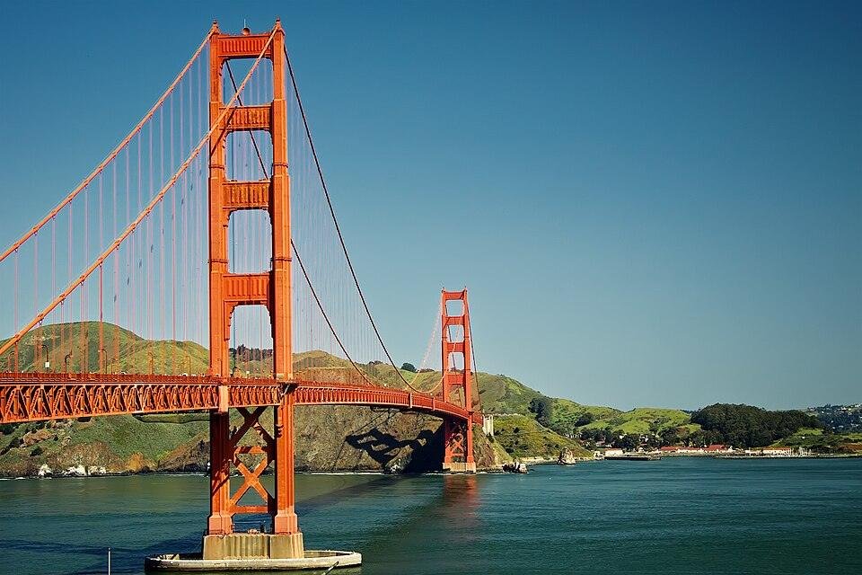
The Golden Gate Bridge is a suspension bridge spanning the Golden Gate strait at the mouth of San Francisco Bay, connecting San Francisco to Marin County in California. Completed in 1937 after four years and four months of construction, it held the title of the world’s longest suspension bridge for 27 years, with a main span of 4,200 feet (1,280 metres). Delivered under a $35 million bond and finished $1.3 million under budget, it draws approximately 15 million visitors annually and generates $2 billion in regional economic impact.
Technical Snapshot: Golden Gate Bridge Core Project Specifications
| Location | San Francisco Bay, California, USA |
| Bridge Type | Suspension bridge |
| Main Span | 4,200 ft (1,280 m) |
| Total Length | 1.7 miles (8,981 ft / 2,737 m) |
| Tower Height | 746 ft (227 m) above water |
| Roadway Clearance | 265 ft (81 m) above mean high water |
| Cable Diameter | 36⅜ in (92.4 cm) per cable |
| Wires per Cable | 27,572 individual galvanised steel wires |
| Total Wire Length | 80,000 miles (129,000 km) across both cables |
| Construction Period | January 1933 – April 1937 |
| Opening Date | May 27, 1937 |
| Original Cost | $35 million (approx. $630 million in 2024 dollars) |
| Chief Engineer | Joseph B. Strauss |
| Structural Designer | Charles Alton Ellis |
| Consulting Architect | Irving F. Morrow |
The Golden Gate Bridge transformed the economic geography of Northern California, unlocking the Marin Peninsula for development while permanently redefining what suspension bridge engineering could accomplish at scale. Its towers, cables, and Art Deco profile remain the defining features of iconic twentieth-century bridge engineering.
Introduction: Suspension Bridge Engineering and the San Francisco Bay
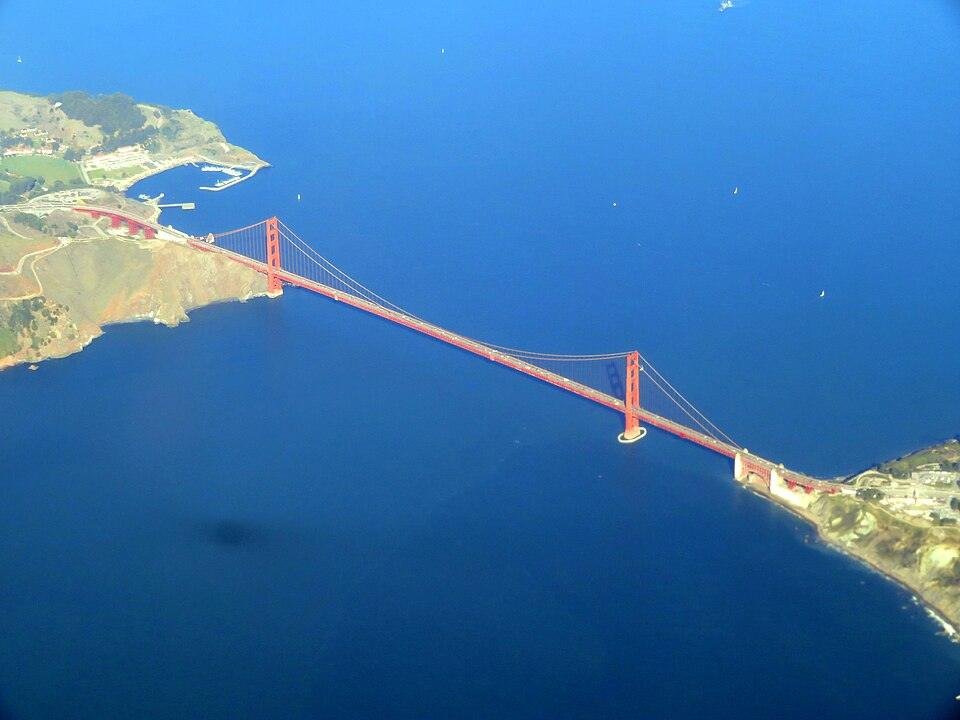
The Golden Gate Bridge did not emerge from a straightforward engineering brief. It emerged from decades of institutional scepticism, financial paralysis, seismic uncertainty, and site conditions that most engineers of the early twentieth century regarded as prohibitive. The strait it crosses is 1.7 miles wide, subject to hurricane-force winds, dense fog, and tidal currents running at 7.5 knots. The bedrock beneath the south pier sits 34 metres below an open, ship-trafficked bay. When construction began in January 1933, the Golden Gate Bridge was an attempt to push suspension bridge engineering into uncharted territory.
Its dimensions alone do not explain what the bridge achieved. The structural choices that made those dimensions possible, the construction methods developed without precedent, and the financial battles that nearly killed the project before the first rivet was driven: these are what separate the Golden Gate Bridge from a large bridge to an engineering threshold, hence its renown among the world’s top iconic engineering structures.
Origins and the Case for a Crossing
The idea of bridging the Golden Gate dates to 1869, but it gained real traction only in 1916, when engineer-turned-journalist James Wilkins reopened the debate with a newspaper campaign. The true catalyst was San Francisco city engineer Michael O’Shaughnessy, who in 1919 began canvassing bridge engineers for a credible cost estimate. Most returned figures were above $100 million. Joseph Strauss, a prolific builder of drawbridges and bascule spans, quoted a cost of $25 to $30 million. That figure won him the commission.
Strauss’s Original Design and Its Transformation
Strauss’s 1921 proposal was a hybrid cantilever-suspension design; his critics called it a “rat trap” for its structural incoherence. The transformation was led by structural engineer Charles Alton Ellis. Working with suspension bridge theorist Leon Moisseiff, Ellis abandoned the hybrid entirely and developed a pure suspension design, refining the structural calculations over several years: stresses in the span, stiffening-truss geometry, tower proportions, and the mathematics of cable tension under live and dead loads.
Strauss fired Ellis in November 1931, before construction began, over what he termed excessive telegraph costs with Moisseiff. Ellis continued working on the calculations without pay and delivered the completed analysis to Strauss at no cost. He received no credit at the 1937 opening. A plaque acknowledging his role was installed at the bridge in 2012, 75 years after the structure opened. The American Society of Civil Engineers has since designated the Golden Gate Bridge a Historic Civil Engineering Landmark.
Financing Through the Great Depression
Bay Area voters approved the $35 million bond in November 1930, as the Great Depression was already contracting credit markets. Commercial lenders would not take the bonds. The project survived because Bank of America founder A.P. Giannini agreed to purchase the entire bond issue, citing the employment the project would create. Construction ran from January 1933 to April 1937 and finished $1.3 million under the authorised budget, a result that the Golden Gate Bridge Highway and Transportation District records as one of the few New Deal-era infrastructure projects completed under cost.
Structural Design of the Golden Gate Bridge
The structural design of the Golden Gate Bridge operates across interdependent load-transfer systems: cable tension, tower compression, truss stiffness, and anchorage resistance. Each system transfers load through a different mechanism. The integrity of the whole depends on all of them performing simultaneously under thermal expansion, wind, seismic movement, and variable traffic loading. The Federal Highway Administration’s bridge safety standards now reference the Golden Gate’s structural approach as a baseline for evaluating long-span suspension bridges.
The Tower System
The two towers rise 746 feet above the water, constructed from structural steel rather than the reinforced concrete used on most large bridge towers of the period. Steel gave the project greater height-to-weight efficiency and the tapered, Art Deco profile that consulting architect Irving Morrow developed. Each tower comprises two hollow steel columns braced by horizontal cells. Morrow integrated the bracing pattern into the tower’s visual rhythm, giving the Art Deco stepped-portal design an explicit structural logic rather than applied ornament.
The towers carry a combined dead load of 44,000 tonnes. Cable tension delivers 61,500 tonnes per tower at the saddles, then transfers downward through the piers into the bedrock below the bay. The tower steel, fabricated in Philadelphia and shipped via the Panama Canal, required specialist marine logistics to reach the open-water pier site, a supply chain constraint that shaped the construction schedule from the outset.
The Cable System
The engineering behind the Golden Gate Bridge is most directly expressed in its cable geometry. Two main cables, every 36⅜ inches in diameter, carry the full suspended load of the deck. Each cable consists of 61 strands of varying sizes, with individual strand wire counts ranging from 256 to 472 wires. Each wire is 0.196 inches in diameter. The combined wire length across both cables reaches 80,000 miles, sufficient to circle the Earth more than three times.
Cable contractor John A. Roebling’s Sons adapted the aerial spinning technique used on the George Washington Bridge two years earlier, but at a rate the profession had not previously achieved. The table below compares the two projects on the parameters that mattered most to the cable-spinning programme:
| Parameter | George Washington Bridge (1931) | Golden Gate Bridge (1937) |
| Cable diameter | 36 in (91.4 cm) | 36⅜ in (92.4 cm) |
| Wires per cable | 26,474 | 27,572 |
| Spinning rate per cable | 61 tons/day | 271 tons/day (4.4× faster) |
| Main span | 3,500 ft (1,067 m) | 4,200 ft (1,280 m) |
| Cable contractor | John A. Roebling’s Sons | John A. Roebling’s Sons |
After spinning, hydraulic jacks applied 4,000 psi and compacted the strands into circular cross-sections. The cables were banded at intervals and wrapped with an outer envelope of galvanised steel wire for corrosion resistance. Vertical suspenders spaced 50 feet apart connect the cables to the stiffening truss, transferring deck loads into the cable system. Cable spinning was completed two months ahead of schedule in May 1936.
The Stiffening Truss and Deck
The roadway deck is stabilised against wind and differential loading by a continuous stiffening truss running the full span length. The truss incorporates approximately 4,700 tonnes of bracing members to resist wind-induced oscillations and the differential deflection between deck panels that can generate resonance. Three years after the Golden Gate Bridge opened, the Tacoma Narrows Bridge collapsed due to wind-induced resonance, a failure directly attributable to inadequate deck stiffening. The Golden Gate’s truss, initially judged conservative, became the standard reference for post-Tacoma suspension bridge design.
The deck sits 265 feet above mean high water at mid-span and is engineered for a maximum design deflection of 3.3 metres. At the bridge’s 50th anniversary in 1987, 300,000 people on the span produced a 7-foot downward deflection at mid-span, flattening the catenary arc. The structure carried the load without damage, a direct confirmation of Ellis’s original margin calculations.
The Golden Gate Bridge Construction History
The Golden Gate Bridge construction history is inseparable from the conditions of the strait itself. This was an exposed, commercially active waterway with deep water, 7.5-knot tidal currents, and a geological profile that demanded foundation work without precedent. San Francisco bridge construction at this scale introduced techniques that became part of the permanent toolkit of suspension bridge engineering worldwide.
The South Pier: Deep-Water Foundation Engineering
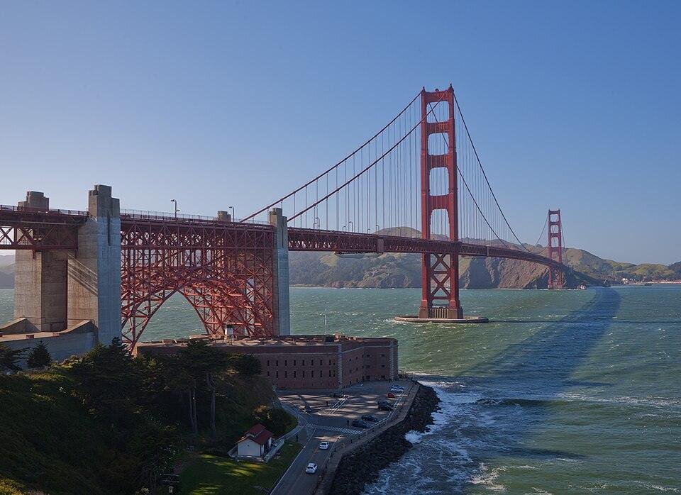
The south pier sits 1,100 feet offshore in open water 34 metres deep. No bridge had previously placed a major structural foundation in open-water conditions of this depth. Engineers first constructed an oval cofferdam, or fender, around the pier site to protect the work area from ship traffic. Workers blasted through the bay floor with explosives, cleared debris with high-pressure hoses, and then placed watertight forms on the sea floor. Crews poured 153,500 cubic yards of concrete to build the pier up through the water column.
On 14 August 1933, a cargo vessel struck the access trestle in heavy fog, causing serious damage and halting work. The pier was completed on schedule, and the deep-water technique it established influenced open-water foundation engineering for decades, as documented in the US Naval Institute Proceedings’ April 1935 analysis of the project’s engineering advances.
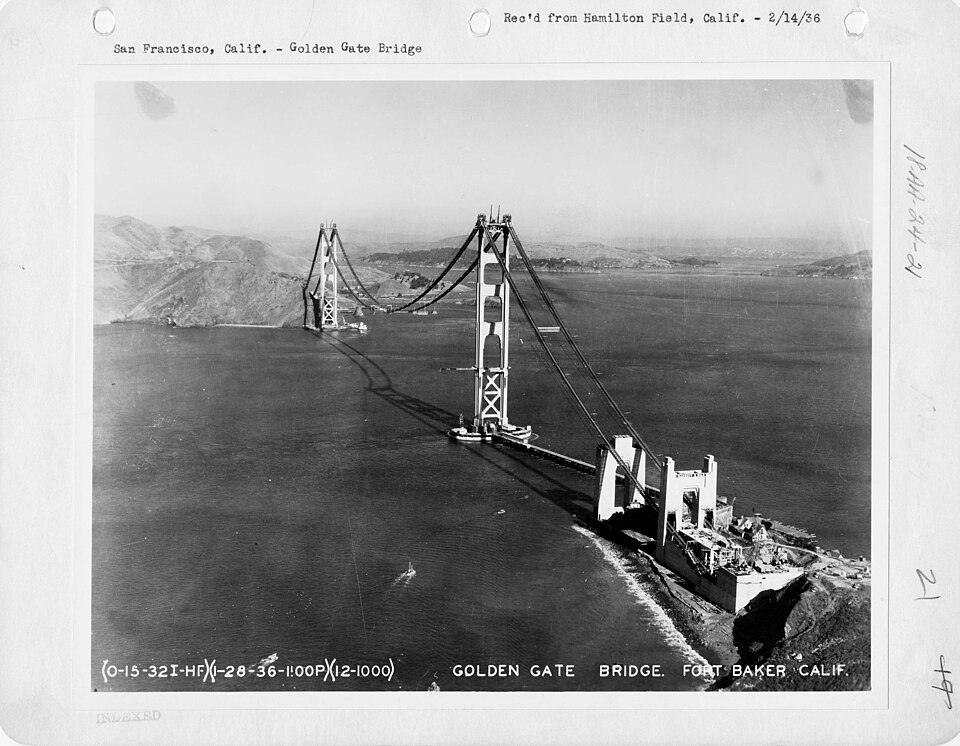
Tower Erection and the Safety Net
Tower erection used creeper derricks that climbed the structure as each section was lifted into position. The Marin tower rose from a land-based foundation; the San Francisco tower required full marine construction logistics on the open-water pier. One of the most consequential decisions of the entire project was installing a safety net under the deck during stiffening-truss construction. The net cost was $130,000, extended 10 feet beyond the trusses on both sides, and saved 19 workers who became known as the “Half-Way-to-Hell Club“. Eleven men still died when a scaffold section failed and fell through the net. The net itself was the first systematic fall-arrest system on a major American bridge project and influenced national construction safety standards.
Construction Timeline
- January 1933: Groundbreaking; south pier fender construction begins.
- March 1933: Tower steel was fabricated in Philadelphia and shipped via the Panama Canal to Alameda, California.
- March 1933–March 1934: The San Francisco tower access trestle was constructed, 1,100 feet offshore.
- January 1934: South pier concrete poured in open water, 34 m below the surface.
- June 1934–June 1935: Both towers erected and completed.
- October 1935–May 1936: Cable spinning completed two months ahead of schedule.
- May 1936–April 1937: Stiffening truss, deck, and roadway were constructed.
- April 19, 1937: Bridge structurally complete.
- May 27, 1937: Pedestrian Day: 200,000 people cross on foot.
- May 28, 1937: Bridge opens to vehicles; Roosevelt signals from Washington, D.C.
Art Deco Architecture and the Decision on Colour
The structural design of the Golden Gate Bridge is the work of engineers. The object people have photographed and identified with San Francisco for nearly ninety years is equally the creation of architects. Irving Morrow’s role extended well beyond selecting a paint colour: he defined the tower’s visual language, the proportions of the portal, and the relationship between the structural elements and the landscape they occupy.
Morrow’s Tower Design
Morrow’s towers are stepped and tapered, with horizontal cross-bracing expressed rather than concealed and chevron-profile portal openings that reduce visual mass without compromising structural capacity. The design sits within the Streamline Moderne strand of Art Deco, emphasising verticality, geometric precision, and the direct expression of industrial materials. The 1,200,000 exposed rivets connecting the tower plates are not decorative; Morrow incorporated them into the surface texture as a machine-age statement. The towers are not decorated engineering marvels; they are engineered architecture.
The Society of Architectural Historians identifies the Golden Gate Bridge towers as among the most significant examples of Art Deco infrastructure in the United States, noting that Morrow’s stepped-portal geometry became a reference point for monumental bridge design in the decade that followed. For a contemporary comparison of how architects achieve structural-aesthetic integration at the civic scale, the Harbin Opera House demonstrates how structural logic can generate architectural identity without applied ornament.
International Orange
The bridge steel arrived primed in a red-orange anti-corrosion coating. The US Navy pushed for black-and-yellow warning stripes; the Army Air Corps wanted alternating red-and-white bands. Morrow argued for retaining the orange primer, which he formalised as “International Orange“: an orange-vermilion tone that reads warm against the grey Pacific fog, harmonises with the rust-coloured Marin headlands, and holds visibility for maritime traffic. His argument prevailed over both military objections.
Maintenance painting is continuous. The Golden Gate Bridge District employs a permanent crew of painters working across the span year-round, addressing sections compromised by salt spray and oxidation. The current seismic retrofit programme requires repainting the south tower above the roadway as part of its scope of work.
Challenges of Building the Golden Gate Bridge
The challenges of building the Golden Gate Bridge were structural features of the project, not incidental obstacles. Each shaped the engineering decisions: foundation depth, cable diameter, deck deflection limits, and tower steel weight. The solutions generated by the project became part of the permanent practice of suspension bridge engineering.
Wind, Fog, and Tidal Conditions
The Golden Gate Strait channels Pacific weather into San Francisco Bay. Wind speeds at the bridge site regularly exceed 60 mph. The design specification required resistance to both static and dynamic wind loads. The stiffening truss managed dynamic wind response by preventing differential deflection between deck panels, which can cause resonance. Fog compounded the construction risk throughout. The August 1933 vessel collision with the access trestle was a direct consequence of reduced visibility. Tidal currents at 7.5 knots limited productive working time at the water surface and required a purpose-built marine plant to hold position during critical operations.
Seismic Risk and the Retrofit Programme
The Golden Gate Bridge sits 7 miles from the San Andreas Fault and 0.6 miles from the Hayward Fault. The original design incorporated seismic resistance through tower mass and anchorage stiffness. The bridge came through the 1989 Loma Prieta earthquake undamaged, though that event was centred 60 miles south. A major rupture closer to the bridge site could impose ground motions that the original structure was not designed to absorb without significant damage.
The seismic retrofit programme began in 1990. The table below sets out the full phase structure, scopes, and costs as documented by the Engineering News-Record and the Golden Gate Bridge District:
| Phase | Period | Scope | Key Works |
| Phase 1 | 1990s | North approach viaduct | Viaduct strengthening, anchorage housing reinforcement |
| Phase 2 | Early 2000s | South side | South approach viaduct, Fort Point arch, south anchorage housing |
| Phase 3A | 2010s | Pylons and north anchorage | North pylon, north anchorage housing upgrades |
| Phase 3B1 | 2026–2031 | Towers and main span | $864M: steel plates to tower bases, 38 energy-dissipation devices, 255 floor beams retrofitted, and the south tower repaint |
| Phase 3B2 | Post-2031 | Main 4,200 ft span | ~$900M: main span structural upgrades; total programme: ~$1.8B. |
Phase 3B1 alone, awarded to Halmar International in 2024, has a contract value of $864 million. The full programme is estimated at $1.8 billion, with funding secured for approximately half. Construction through Phase 3B2 is projected to run to 2036. The Construction Equipment Guide reports that Phase 3B will install micropiles to reinforce foundations and replace expansion joints to allow three-dimensional seismic movement at the tower bases.
Engineering Legacy and Global Influence
The Golden Gate Bridge did not merely set a span record. It established a methodology for suspension bridge engineering at the frontier of structural scale: cable-spinning rates, deep-water foundation techniques, safety-net practices, and the integration of seismic analysis into bridge design. These advances shaped the profession for three decades, and their consequences remain visible in current practice.
Influence on Suspension Bridge Design
The Golden Gate Bridge held the world record for longest suspension span from 1937 to 1964, when the Verrazano-Narrows Bridge in New York surpassed it. In that period, the techniques and proportions it established became the reference for major suspension bridge projects worldwide. The cable-spinning rates John A. Roebling’s Sons achieved on the Golden Gate remained benchmarks for later projects.
Leon Moisseiff’s deflection theory, which informed Ellis’s structural calculations and permitted a lighter, more slender deck than earlier suspension bridges, was implicated in the 1940 Tacoma Narrows collapse when applied without aerodynamic analysis. The engineering profession’s response was not to abandon deflection theory but to require independent aerodynamic assessment for all long-span decks. Wind tunnel testing of bridge decks, now a standard requirement, is a direct product of that reassessment. The Golden Gate’s stiffening truss, initially considered conservative, became the design model. The Tacoma-Golden Gate comparison is a pivotal case study in twentieth-century suspension bridge aerodynamics.
Comparing structural decisions across iconic projects reveals how one structure’s choices frame the next generation’s brief. The Sydney Opera House‘s shell geometry and the Dubai Opera House‘s contemporary performance envelope both reflect the accumulated discipline of structural innovation, in which an engineering threshold set by one project becomes the assumed minimum for the next.
Economic and Urban Development Impact
Before the Golden Gate Bridge opened, Marin County was accessible only by ferry. Development north of the bay was constrained by access costs and crossing time. The bridge cut the journey to minutes and transformed the land-use economics of the entire North Bay. Marin, Sonoma, and Napa counties developed at densities directly dependent on road connectivity through the crossing.
The National Park Service reports that Golden Gate National Recreation Area, which includes the bridge and its approaches, attracted approximately 15 million visitors in 2023. Current traffic and economic figures are set out below:
| Metric | Figure (2023–2024 data) |
| Annual vehicle crossings | ~32 million (44,000 southbound daily) |
| Total crossings since 1937 | Over 2.26 billion |
| Annual toll revenue | Over $150 million |
| Annual visitors (GGNRA) | ~15 million |
| Direct visitor spending | $1.5 billion (NPS, 2023) |
| Cumulative economic benefit | $2 billion to local communities |
| Jobs supported | 13,150 (NPS estimate, 2023) |
| Original construction cost | $35 million (1937); ~$630 million in 2024 dollars |
The bridge cost $35 million to build in 1937 dollars. The returns on that investment, measured in toll revenue, regional development uplift, and tourism-driven economic activity, are orders of magnitude larger. No single infrastructure project in Northern California has had a more sustained influence on the region’s development trajectory.
Conclusion: What the Golden Gate Bridge Represents for Structural Engineering
The Golden Gate Bridge construction history set the terms for suspension bridge design for three decades. The engineering behind the Golden Gate Bridge produced cable-spinning rates, foundation techniques, stiffening methodologies, and site safety practices that the profession absorbed and applied to every major suspension bridge that followed. Its Art Deco aesthetic, achieved by integrating structural logic with architectural intent, produced a bridge that is simultaneously functioning infrastructure and a recognised cultural monument.
The seismic retrofit programme, now approaching $1.8 billion across four construction phases, confirms the engineering community’s judgement on its continued relevance. The Golden Gate Bridge is not being preserved as a heritage artefact: it is being upgraded to twenty-first-century seismic performance standards as functioning road infrastructure. That position reflects the soundness of Ellis’s original structural concept, which has proved extensible and adaptable across nearly ninety years of operation, load growth, and revised seismic codes.
For a study in how structural design can convert a hostile site condition into a defining architectural identity, the InterContinental Shanghai Wonderland Hotel inverts a quarry void into a vertical hospitality structure. The Golden Gate Bridge made the same move at a civic scale: the most technically demanding strait on the Pacific coast became home to the most recognised suspension bridge in the world.
Explore More Iconic Bridge Engineering Projects
Discover how the world’s greatest bridges, megaprojects, and civil engineering landmarks are transforming global infrastructure with Construction Frontier: Global Mega Projects. Explore deep technical analysis, structural innovations, and the engineering brilliance behind the most iconic structures shaping the modern built environment.