Hoover Dam: Monumental Concrete Engineering Behind America’s Most Ambitious Dam Project
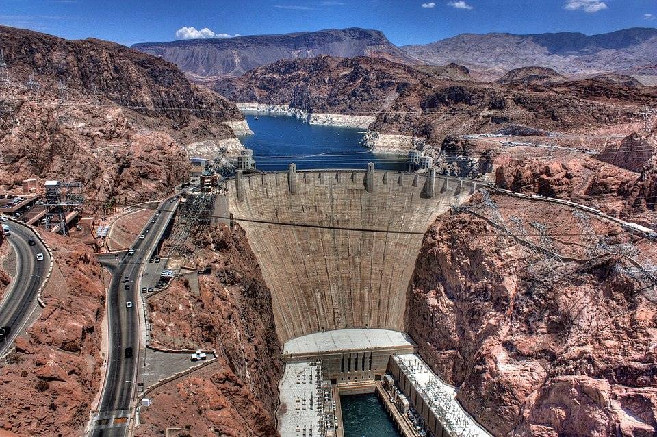
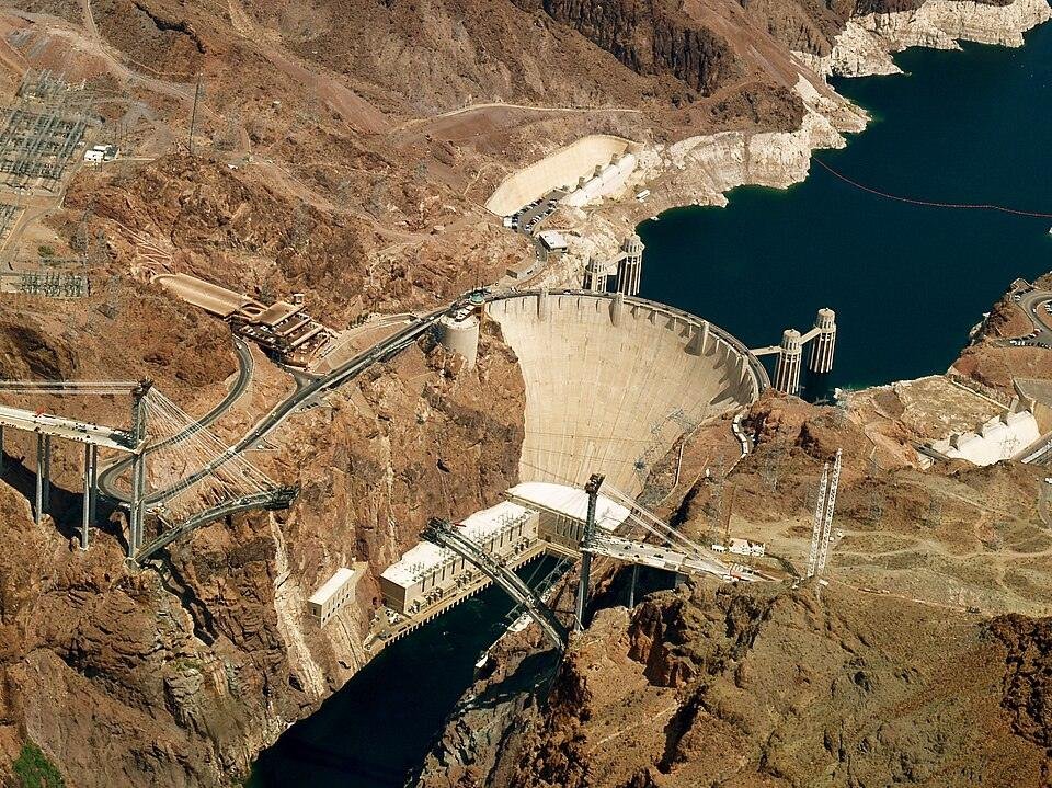
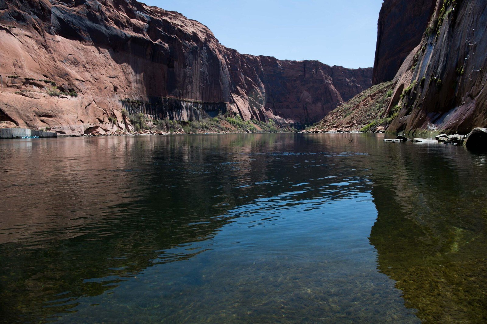
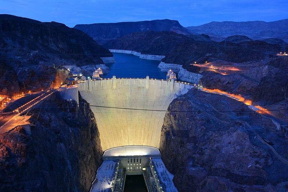
Hoover Dam stands 726 feet above the bedrock of Black Canyon on the Nevada-Arizona border, a concrete arch-gravity structure that impounds the Colorado River behind the largest reservoir in the United States. Completed in 1935, two years ahead of schedule, the Hoover Dam project consumed 3.25 million cubic yards of concrete and deployed construction innovations that continue to define concrete dam engineering globally. Its 17 Francis-type turbines deliver up to 2,080 megawatts of hydroelectric capacity, supplying power to three states and water to over 40 million people.
Technical Snapshot: Hoover Dam Core Project Specifications
| Specification | Detail |
| Dam Type | Concrete arch-gravity (curved upstream plan with gravity mass) |
| Height above Bedrock | 726.4 ft (221.4 m) |
| Crest Length | 1,244 ft (379 m) |
| Base Width | 660 ft (201 m) |
| Crest Width | 45 ft (14 m) |
| Concrete Volume (dam only) | 3.25 million cubic yards (2.48 million m³) |
| Concrete Volume (all structures) | 4.4 million cubic yards (3.36 million m³) |
| Portland Cement | More than 5 million barrels |
| Aggregate Used | 4.5 million cubic yards |
| Reinforcing Steel | 45 million lb |
| Cooling Pipe Network | 582+ miles of 1-inch steel pipe embedded in concrete |
| Column Block Dimensions | 60 ft sq (upstream face) to 25 ft sq (downstream face) |
| Maximum Lift Height per Block | 5 ft per 72-hour cycle |
| Hydroelectric Capacity | 2,080 MW (17 Francis-type turbines) |
| Annual Generation | ~4 billion kWh (enough for ~1.3 million people) |
| Reservoir (Lake Mead) | 28.9 million acre-feet; largest US reservoir by volume |
| Hydraulic Head Range | 304 ft (min pool) to 590 ft (full reservoir) |
| Construction Period | 1931–1935 (handed over to the US government: 1 March 1936) |
| Construction Cost | $49 million (1931); ~$811 million in 2024 dollars |
| Workforce | ~21,000 workers across the project life |
| Contractor | Six Companies, Inc. (consortium of 7 firms in 6 partners) |
| Late Penalty Clause | $3,000 per day for overrun on diversion tunnel schedule |
| Recognition | ASCE National Historic Civil Engineering Landmark; National Historic Landmark |
Hoover Dam did not just tame a river; it demonstrated that concrete dam engineering on an unprecedented scale was achievable, establishing the construction methods, material specifications, and structural analysis frameworks that still inform hydroelectric dam engineering worldwide.
Introduction: Iconic American Engineering Project
The Hoover Dam belongs to a short list of structures where ambition, necessity, and invention arrived at the same moment. In the early 1930s, the Colorado River still flooded Imperial Valley farmlands every spring and withheld water through drought cycles that damaged irrigation infrastructure across three states. Washington needed a structure that could simultaneously control floods, store water for irrigation, and generate electricity for a region that had almost none. What engineers designed was not merely a dam. It was the largest concrete structure ever attempted, a project that exceeded the masonry mass of the Great Pyramid of Giza, securing its place among the world’s most iconic structures, and required the near-complete reinvention of concrete placement methodology.
The Bureau of Reclamation selected Black Canyon over the originally proposed Boulder Canyon site for its narrower gorge, superior foundation geology, andesite and rhyolite bedrock that could bear extreme load, and its proximity to the Las Vegas rail terminus. In March 1931, the contract went to Six Companies, Inc., a consortium of seven construction firms organised into six partners: the only procurement arrangement capable of raising the required $5 million performance bond. Construction superintendent Frank Crowe, who had built more dams than any engineer of his generation, brought the project to completion two years ahead of the contracted deadline. The history and impact of the Hoover Dam project resonate through every major hydroelectric infrastructure programme built since.
The Engineering Problem: Why Conventional Concrete Dam Design Could Not Scale
The central challenge of the Hoover Dam was not structural conception but material physics. Engineers at the Bureau of Reclamation recognised early in the design process that the scale of concrete placement required for a dam of this height posed a thermodynamic crisis without precedent in the history of infrastructure projects. Chief design engineer John L. Savage and Professor Raymond Davis of UC Berkeley ran a joint research programme from 1931, producing new specifications for cement chemistry, heat-of-hydration management, aggregate sizing, and mix proportions before a single cubic yard could be placed. Every aspect of the concrete engineering behind Hoover Dam was invented, not adapted.
Thermal Management: The Column-Pour and Cooling Pipe System
Portland cement releases heat during hydration as concrete sets. In small pours, ambient temperature dissipates this without consequence. At Hoover Dam’s volumes, Bureau engineers calculated that a monolithic continuous pour would have generated sufficient internal heat to crack the structure from within. Their projection, documented by the Bureau of Reclamation, indicated that natural cooling from a single continuous pour would have taken 125 years.
The solution defined how Hoover Dam was constructed and set a precedent that subsequent large concrete dams have followed. Engineers divided the dam into interlocking trapezoidal columns, varying from 60 feet square at the upstream face to 25 square feet at the downstream face, rising in five-foot lifts with a mandatory 72-hour interval between successive lifts on any single block. Within each column, workers embedded one-inch steel pipes through which chilled river water and, later, refrigerated water from a plant producing 1,000 tonnes of ice per day circulated as the concrete set.
Once hardening was complete, the pipes were pressure-grouted with a cement slurry, becoming permanent structural elements. More than 582 miles of cooling pipe ran through the dam’s mass. After cooling, grout was injected through perforated pipes in every vertical and horizontal joint; once set, the blocks contracted and locked into a single monolith. The engineering challenges of Hoover Dam construction in thermal management alone led to techniques that define mass concrete practice globally today.
The Arch-Gravity Structural Form and Trial-Load Analysis
Hoover Dam’s arch-gravity classification reflects a dual load-transfer mechanism. A gravity dam resists hydrostatic pressure through mass. An arch dam transfers load laterally into the canyon abutments. The hybrid exploits both: the curved upstream plan transmits a portion of the Colorado River’s pressure into the canyon walls, while the concrete mass absorbs the remainder. At 660 feet thick at the base, tapering to 45 feet at the crest, the geometry reflects precise optimisation.
As Engineering News-Record documented in 1932, the design team developed new mathematical equations, stress analysis methods, and model-testing protocols to validate this form. The trial-load analysis required simultaneous resolution of tangential shear, twist, Poisson’s ratio, concrete creep, radial cantilever behaviour, foundation deformation, earthquake loading, and upstream canyon wall pressure. No existing framework covered all of these. The team built the analytical methods alongside the dam itself.
Structural Engineering: Arch-Gravity vs Pure Gravity vs Pure Arch
| Parameter | Arch-Gravity (Hoover) | Pure Gravity Dam | Pure Arch Dam |
| Load transfer | Combined: mass + lateral arch thrust into abutments | Mass only; no lateral transfer | Lateral thrust only into abutments |
| Concrete volume efficiency | Reduced vs pure gravity (arch reduces mass needed) | Maximum; relies entirely on weight | Minimum; thinnest section possible |
| Foundation requirement | Strong rock abutments AND base | Strong base; abutments less critical | Extremely strong, rigid rock abutments essential |
| Seismic behaviour | Moderate; mass provides damping; arch distributes the load. | Low vulnerability; mass absorbs energy | Higher risk; abutment failure is catastrophic |
| Canyon suitability | Ideal for narrow gorges; abutments close together | Less efficient; wide cross-section needed | Ideal; maximum span efficiency |
| Precedent at Hoover Dam scale (1931) | None; new analysis required | Established for lower dams | No precedent at this height |
River Diversion and Site Preparation: The Work Before the Dam
Hoover Dam construction could not begin on a live river. The Colorado had to be completely bypassed before foundation excavation or concrete placement could start, a task that ranked among the most demanding engineering challenges of the twentieth century. The contract imposed a $3,000-per-day penalty for any overrun on the diversion tunnel schedule, a financial pressure that drove the most aggressive tunnel excavation programme in American history up to that point.
The Diversion Tunnels
Bureau engineers designed four diversion tunnels, two through each canyon wall, every 56 feet in diameter and concrete-lined. Their combined length approached 16,000 feet: over three miles. Frank Crowe’s key contribution to their execution was drilling Jumbo, a ten-storey platform mounted on a truck chassis carrying up to 30 pneumatic drill operators, attacking the rock face simultaneously across multiple elevations. The four tunnels were completed ahead of the contractual October 1933 deadline, diverting the full Colorado and exposing the canyon floor. The two inner diversion tunnels were later repurposed as permanent penstock and outlet works, eliminating the need for separate tunnel construction and reducing total material costs. Full specifications are on the Bureau of Reclamation tunnel records.
Foundation Excavation and the High Scalers
With the river diverted, crews confronted fractured, weathered canyon walls that could not withstand the load from a 726-foot dam. Over 100 feet of riverbed silt, sand, and broken rock were excavated to reach competent bedrock; abutment preparation took a full year and was completed in mid-1933. This operation produced the most exposed role on the project: the high scalers.
Suspended on ropes from the canyon rim, sometimes 800 feet above the riverbed, they used 44-pound jackhammers to strip loose material from the canyon walls before anchoring could begin. Without their work, no reliable arch load transfer to the abutments was possible. There was no safety net, no fall-arrest system, and no precedent for working at this height on active blasting terrain.
Further Reading: Grand Inga Dam in the DRC: Africa’s Ambitious Mega Project Set to Transform Energy
Concrete Placement at Scale: Mix Design, Logistics, and Innovation
The concrete dam engineering behind Hoover Dam was as much a logistics problem as a technical one. Moving 3.25 million cubic yards of concrete from the mixing plant to formwork in a remote desert canyon, with no pre-existing infrastructure, at a pace fast enough to stay ahead of schedule required production and delivery systems with no equivalent in the industry. Engineers averaged 6,000 cubic yards of concrete per day, a throughput that required every element of the supply chain to operate simultaneously without interruption.
Mix Design and Cement Specification
Chief designing engineer Savage specified four sacks of cement per cubic yard for the mass concrete, each sack weighing 96 pounds, yielding 376 pounds of cement per cubic yard. The cement specification called for low-heat formulations after initial sections showed excessive thermal response, a requirement that contributed directly to the Bureau’s development of modern low-heat cement standards.
Aggregate, up to three-quarters of the dam’s mass by volume, came from an alluvial deposit six miles upstream on the Arizona bank, where rounded stones up to 12 inches in diameter had washed down from the Grand Canyon over millennia. The Bureau’s concrete research programme, run with UC Berkeley under Professor Davis, examined every variable from maximum aggregate size to water ratio, producing a specification body that became the reference standard for mass concrete in large dams worldwide.
The Automated Plant and Cableway Delivery System
A fully automated mixing plant on the canyon rim could produce 24 cubic yards every three and a half minutes. Five 20-tonne cableways delivered a fresh eight-cubic-yard bottom-dump bucket to the designated column every 78 seconds, sustaining the 6,000-cubic-yard daily average that kept the project on schedule. Concrete placement began on 6 June 1933. Five million barrels of Portland cement and 4.5 million cubic yards of aggregate passed through this system, consuming more cement than the Bureau of Reclamation had used across all 27 years of its prior construction activity.
The concrete engineering behind Hoover Dam was, in this sense, an industrial production problem of the same order as the structural one, and the speed of delivery became its own engineering achievement. As the Bureau of Reclamation records document, placement ran steadily from June 1933 through to completion in 1935, never falling significantly behind the required pace.
Quality Control and the Self-Hardening Concrete
Every batch received pre-pour testing; the Bureau maintained strict mix specifications to ensure density and long-term compressive strength. The result was a concrete matrix so thoroughly proportioned that its pozzolanic hydration reactions have never fully ceased. The dam now withstands hydrostatic pressures of up to 45,000 psi and grows marginally stronger with each year.
This longevity connects the concrete engineering behind Hoover Dam to a broader engineering truth: the decisions made at the mix-design stage outlast every other element of a project. It places the dam alongside more recent structures that demand the same precision in concrete-to-geology interfaces, including subterranean projects such as the InterContinental Shanghai Wonderland, where engineered concrete performance at depth was the critical design constraint.
Mass Concrete Engineering: Hoover Dam vs Subsequent Major Dams
| Parameter | Hoover Dam (1935) | Grand Coulee (1942) | Itaipu (1984) | Three Gorges (2006) |
| Dam height (m) | 221 | 168 | 196 | 185 |
| Concrete volume (all structures, million m³) | 3.36 | 8.09 | 12.3 | 27.2 |
| Thermal control method | Embedded 1-inch cooling pipes; chilled water circulation; 5-ft block pours | Derived from the Hoover method; expanded cooling grid | Pre-cooling of aggregate; post-cooling pipes | Ice-water cooling + low-heat cement; built on Hoover precedent |
| Column/block system | Yes; 25–60 ft sq blocks; 5-ft lifts; joint grouting | Yes; adapted the Hoover methodology | Monolith sections with contraction joints | Block pours with joint grouting |
| Installed hydroelectric capacity | 2,080 MW | 6,809 MW | 14,000 MW | 22,500 MW |
| Primary construction innovation | Arch-gravity trial-load analysis; cooling pipe system; cableway delivery | The largest gravity dam by volume at the time | Largest installed capacity at the time | Largest installed capacity globally |
Hydroelectric Dam Engineering: Penstocks, Turbines, and Power Distribution
The hydroelectric infrastructure integrated into Hoover Dam was as technically demanding as the dam structure itself. Converting a hydraulic head that varies between 304 and 590 feet into grid-scale electricity required large-bore steel penstocks fabricated on-site, a novel valve system, and transmission infrastructure that did not yet exist across much of the American Southwest. Hydroelectric dam engineering at this scale was largely theoretical in 1935. Hoover Dam proved it worked.
The Penstock and Intake System
Four reinforced concrete intake towers, each 380 feet tall, rise from the floor of Lake Mead, one pair on each side of the canyon. Water enters through 32-foot-diameter cylindrical gates protected by trash racks, then descends into 30-foot-diameter steel penstocks fabricated by Babcock and Wilcox and installed inside the repurposed inner diversion tunnels.
Butterfly valves, 14 feet in diameter, regulate flow to individual turbines. Six giant needle valves in each valve house can discharge up to 15,500 gallons per second, projecting a water jet 450 feet to the opposite canyon wall for flood control and bypass operations. Each spillway on the canyon rim can pass 200,000 cubic feet of water per second, twice the maximum recorded flow of Niagara Falls (293,000 cubic feet per second).
The Generator Hall and Power Distribution
The U-shaped powerhouse, 650 feet long on each wing and rising 299 feet above foundation level, contains 17 Francis-type vertical turbines: nine in the Arizona wing and eight in the Nevada wing. Combined installed capacity reaches 2,080 megawatts. From 1939 to 1949, the plant was the world’s largest hydroelectric installation; it remains one of the largest in the United States. Annual output averages 4 billion kilowatt-hours. Distribution, governed by the Hoover Power Allocation Act of 2011, sends roughly 56% to California, 25% to Nevada, and 19% to Arizona, with the allocations subdivided among utilities, tribal authorities, and municipal water agencies.
The dam ramps generation up or down within minutes, making it a critical grid-stability resource that thermal plants cannot replicate. This operational integration of a dam’s structural form with its power function shares conceptual lineage with other engineered iconic landmarks where structure and programme are resolved as one system, such as the Harbin Opera House, where the building skin and acoustic chamber are the same structural element.
Hoover Dam Power Distribution by Region
| Region / Category | Approximate Share | Key Recipients |
| California | ~56% of total generation | Los Angeles, Southern California Edison, Metropolitan Water District, municipal utilities |
| Nevada | ~25% of total generation | Colorado River Commission; Las Vegas utilities; tribal authorities; Boulder City |
| Arizona | ~19% of total generation | Arizona Power Authority; Salt River Project; Central Arizona Water Conservation District; tribal utilities |
| Total installed capacity | 2,080 MW across 17 turbines | Governed by Hoover Power Allocation Act (2011); contracts managed by US Dept. of Energy |
| Annual generation (average) | ~4 billion kWh | Sufficient for approximately 1.3 million households |
| Minimum operational pool | 950 ft above sea level (Lake Mead) | Below this elevation, turbine operation ceases; active monitoring as of May 2026 |
The Human Cost of How Hoover Dam Was Constructed
The engineering record of how Hoover Dam was constructed cannot be separated from the human one. Over 21,000 workers passed through the project across five years, drawn to Black Canyon during the Great Depression by wages above the national average but earning in conditions that pushed every physical limit. Hoover Dam construction was never safe; what changed over the project’s life was only the nature of the hazard.
Working Conditions in Black Canyon
Canyon work surface temperatures regularly exceeded 120 degrees Fahrenheit; tunnel temperatures reached above 140. Workers who arrived before Boulder City was built lived in Ragtown, a camp of tents and salvaged materials on the canyon floor. Carbon monoxide from diesel equipment accumulated in the diversion tunnels to dangerous concentrations; Six Companies classified the resulting fatalities as pneumonia, a designation that concealed the industrial cause. In August 1931, workers walked out in protest, as documented in the PBS American Experience archive: the first major labour action on a federal construction project of this scale. The company faced a $3,000-per-day penalty for every day the diversion tunnels ran late, which converted directly into round-the-clock pressure on the workforce.
Fatalities and the Official Record
The official death toll stands at 96 workers, killed by falls, drownings, heatstroke, blasting accidents, and equipment failures. The first recorded fatality occurred on 20 December 1921, during survey work, when geologist J.G. Tierney drowned in the Colorado. The last occurred on the same date in 1935, when Patrick William Tierney, J.G.’s son, fell from an intake tower on the Arizona side. Their names appear together on a memorial plaque near the dam. The monument on the Nevada side bears the message: “They died to make the desert bloom.” That inscription captures the central contradiction of this historic infrastructure project: achievement on a scale the era could not have delivered without the human cost it exacted.
Legacy and Ongoing Challenges: Hoover Dam in the Twenty-First Century
The history and impact of the Hoover Dam project extend far beyond 1935. For nine decades, the dam has met every stated engineering objective: flood control, irrigation storage, and power generation. Its dual designation as an ASCE National Historic Civil Engineering Landmark and a National Historic Landmark reflects a settled consensus that no other American infrastructure project of the twentieth century combined structural innovation, scale of construction, and societal consequence to the same degree. The challenge it now faces emerged from precisely the data the original designers relied on most heavily.
The Water Crisis and Hydropower Decline
Lake Mead supplies water to over 40 million people across Nevada, Arizona, California, and northern Mexico and irrigates millions of acres of farmland. Since 2000, persistent drought and over-allocation of Colorado River water rights have progressively reduced the reservoir’s volume. As of May 2026, the Bureau of Reclamation’s 24-month study on the Colorado River basin projects Lake Mead could fall to 1,021 feet above sea level by summer 2027, shattering the 2022 record low by more than 20 feet.
A Bureau of Reclamation spokesman confirmed that hydropower efficiency is already down approximately 33% from peak capacity. Projections indicate a potential 40% further reduction in hydropower output as soon as autumn 2026 if upstream releases from Lake Powell continue at reduced rates. The plant currently generates enough power for approximately 675,000 homes, down from a peak of one million.
Turbine Upgrades and the Limits of Adaptation
Between 1986 and 1993, the Bureau uprated all of Hoover Dam’s original turbines, replacing them with wide-head Francis units that maintain efficiency across a broader hydraulic head range. These units sustain productive generation at reservoir elevations that would have made the original equipment uneconomical. The upgrade programme confirms a broader truth about iconic American engineering projects: longevity depends not only on original construction quality but also on the ability to adapt to operating conditions the designers never anticipated.
The dam’s concrete shows no structural distress; it continues to harden. The risk is hydrological. A water-allocation framework calibrated to 1920s Colorado River flow data cannot accommodate a climate-driven reduction in that flow without consequences. The parallel with other long-lived infrastructure is direct. The Cahora Bassa Dam, operating on the Zambezi since 1974, faces the same category of challenge: a structure that performs precisely as designed, under river conditions that no longer match the hydrological record on which the design was built.
Further Reading: Cahora Bassa Dam: Remarkable Powering of Southern Africa’s Energy Network
Hoover Dam Influence on Global Concrete Dam Engineering
The engineering innovations developed specifically for the construction of Hoover Dam propagated through the international dam engineering community and directly shaped the design and construction methodology of every large concrete dam built in the following century. The column-pour technique with embedded cooling pipes became standard practice for mass concrete placement. The low-heat cement specifications influenced cement manufacturing standards globally. The trial-load arch-gravity analysis methods refined for Hoover Dam informed the design of Grand Coulee, Three Gorges, Itaipu, and dozens of other projects built since.
The Six Companies consortium model, in which seven firms were organised into six partners to bid on a project that no single contractor could execute, became the template for joint-venture contracting on large public infrastructure projects. That procurement structure now dominates mega-project delivery globally. The engineering challenges of Hoover Dam construction resonate directly in the most ambitious hydroelectric projects currently being planned and developed. The Grand Inga Dam on the Congo River, with a proposed capacity of over 40,000 MW, draws on the same analytical foundations that Hoover Dam’s engineers built from first principles in the early 1930s. The concrete dam engineering knowledge base assembled at Black Canyon is the technical foundation on which those projects will stand.
The project also demonstrated that architecture and structural engineering are not competing disciplines at this scale. Gordon Kaufmann’s Art Deco treatment of the powerhouse and intake towers made Hoover Dam one of the most visited engineered structures in the world, with approximately 7 million tourists annually, according to National Park Service records. That integration of design intent with structural rigour parallels what later iconic projects achieved in other sectors: the Sydney Opera House proved that an engineered structure can become a cultural landmark of equal standing to any purely architectural work, provided structural logic and design ambition are resolved as a single problem rather than competing demands.
Conclusion: What Hoover Dam Tells Engineers About Scale, Risk, and Legacy
Hoover Dam was not cautious. It was a decision to attempt something no existing method could deliver, using a workforce in extreme conditions, on a timeline that left no room for the failures any honest engineer would have expected. The concrete dam engineering it produced, the column-pour system, the embedded cooling network, and the arch-gravity structural analysis were genuine inventions under pressure. The history and impact of the Hoover Dam project cannot be separated from that context.
The concrete is still hardening. The turbines still generate power. The reservoir still supplies water to tens of millions of people. Nine decades of unbroken operation confirm the quality of the engineering judgements made at the Bureau of Reclamation in the late 1920s. The challenge now is systemic: a water allocation framework built on river flows that climate change is making obsolete. That does not diminish what was built. It reframes the question the engineers answered. They solved the problem their era gave them. The engineers working on the Colorado River system today must solve the problems that their predecessors’ solutions helped create.
Stay Updated on Iconic Engineering Megaprojects
Stay ahead of the world’s most ambitious infrastructure and engineering megaprojects with Construction Frontier: Global Mega Projects. Explore deep technical analysis, construction innovations, and the iconic structures redefining modern civil engineering across America and the global built environment.