The World’s Most Iconic Engineering Structures: Stunning Architecture, Innovation, and Legacy
The world’s most iconic engineering structures span every continent, every era, and every scale of human ambition. From a 324-metre wrought-iron tower that transformed structural thinking about wind loads to an 828-metre supertall that redefined the city skyline, each of the world’s most iconic engineering structures shares one defining quality: it solved a problem no one had solved before. These famous engineering marvels have collectively generated the structural knowledge that underpins every major design project today.
Technical Snapshot: Core Project Specifications
| Specification | Detail |
| Structures covered | Eiffel Tower, Golden Gate Bridge, Sydney Opera House, Burj Khalifa, Channel Tunnel, Hoover Dam, Maraya Concert Hall, Harbin Opera House, Dubai Opera House, Shanghai Wonderland Hotel |
| Geographic spread | Europe, North America, Asia-Pacific, Middle East |
| Height range | 27 m (Shanghai Wonderland, below grade) to 828 m (Burj Khalifa) |
| Span range | 4,200 ft main span (Golden Gate) to 50.45 km total length (Channel Tunnel) |
| Construction periods | 1887 (Eiffel Tower) to 2019 (Maraya Concert Hall) |
| Primary keyword | iconic engineering structures |
| Article cluster | Iconic structures & architectural landmarks |
The world’s most iconic engineering structures did not simply change the built environment. Each one forced a reconsideration of what materials, geometry, and human organisation can achieve, and that structural legacy continues to shape every major architectural engineering achievement commissioned today.
Introduction: Iconic Structures & Architectural Landmarks
What makes an engineering structure iconic is not size. World engineering landmarks earn their status not from critics but from the profession, which adopts their methods, cites them in feasibility studies, and trains engineers on the basis of their structural case histories; it is a consequence.
The structures in this article introduced methods that became industry standards, exposed the limits of theories engineers had accepted too uncritically, and, in several cases, forced their own designers to scrap months of work and start again. The path to a global structural masterpiece is not linear, and several of the projects covered here were, at various points, embarrassments: years late, catastrophically over budget, and structurally incomplete. What separated them from ordinary failures was that the engineers kept solving the problem.
This article covers ten of the world’s most iconic engineering structures across five categories: towers, bridges, performing arts venues, water infrastructure, and context-driven engineering. Each is examined through the specific technical decision that made it consequential and through the knowledge that decision generated in the profession that followed. The engineering behind iconic structures is not a museum piece. It is the foundation on which every supertall, every long-span bridge, and every precision cladding system in design today is built.
1. Towers: Engineering the Vertical Frontier
Every tall structure is a negotiation with the wind, and the towers that become world engineering landmarks are defined not by height but by what the engineering team invented to reach them. The Eiffel Tower was the first structure in history designed primarily around wind analysis rather than gravity loads. 120 years later, the Burj Khalifa took that principle to 828 metres, and the conceptual line between the two iconic engineering structures remains unbroken.
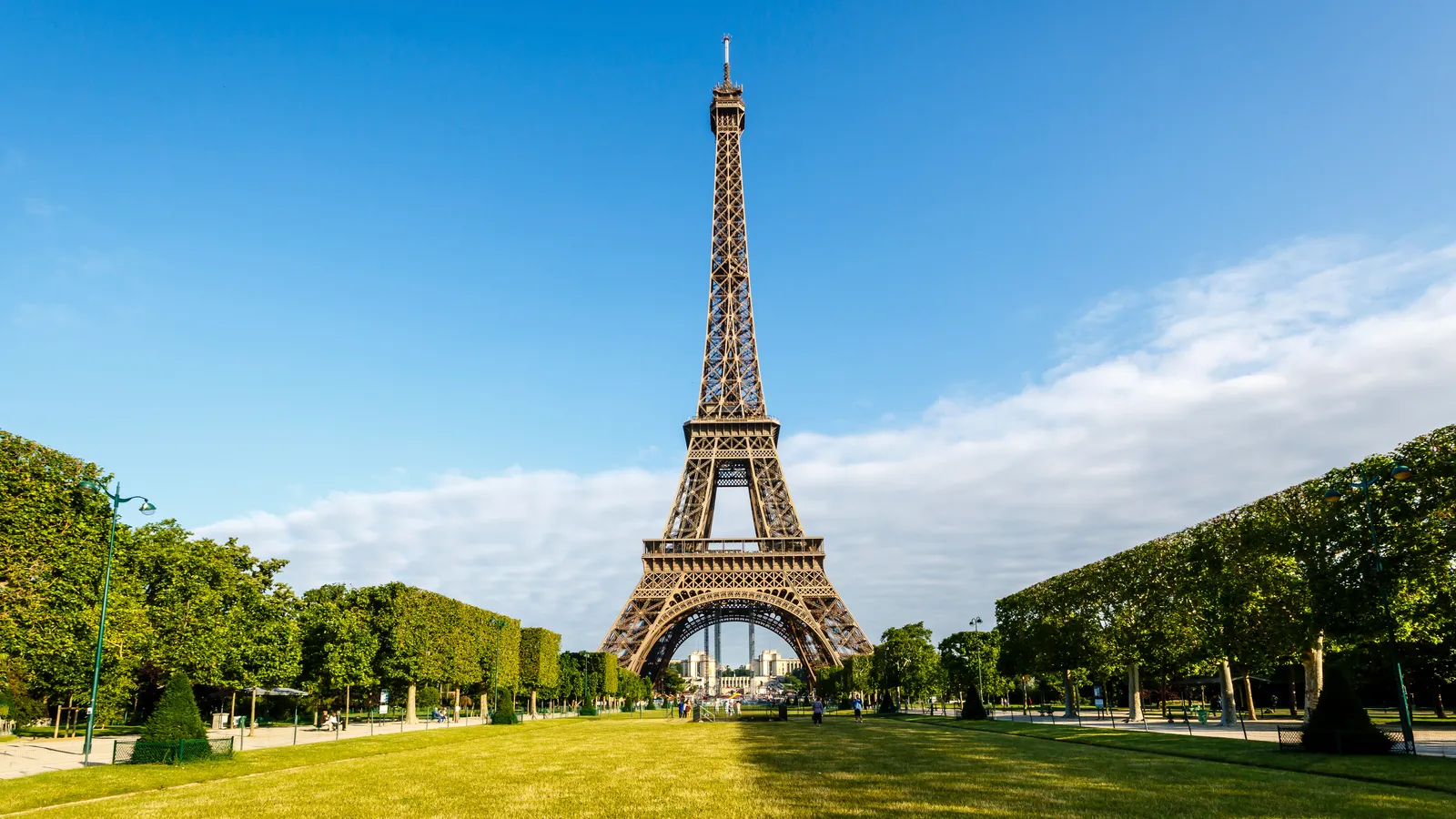
1.1 The Eiffel Tower: Wrought Iron, Wind Loads, and a Revolution in Structural Logic
Three hundred architects signed a public letter opposing the Eiffel Tower before a single rivet was driven. Their objection was aesthetic, but it also stemmed from a failure to understand that Eiffel had not built a monument: he had solved a structural problem and expressed it in iron. Among iconic engineering structures, the tower is unusual in that its form is dictated entirely by calculation.
Eiffel Tower: Technical Data
| Parameter | Value |
| Total height (incl. antenna) | 324 m |
| Iron components | 18,038 individually crafted pieces |
| Rivets | 2.5 million thermally assembled |
| Total iron weight | 7,300 tonnes |
| Foundation pressure | Equal to a seated person per cm² |
| Wind sway tolerance | 6–7 cm at peak |
| Construction period | January 1887 – March 1889 (26 months) |
| On-site fatalities | 1 |
| Record held | World’s tallest structure, 1889–1930 (41 years) |
| Annual visitors | 7+ million (most-visited paid monument globally) |
| Designer | Gustave Eiffel (structural engineer: Maurice Koechlin) |
The tower’s 18,038 components weigh 7,300 tonnes. Eiffel chose wrought iron because it matched stone in compressive strength at a fraction of the weight and cost. The structure exerts no more pressure per square centimetre on its foundations than a seated person on a chair.
The four legs curve inward in a parabola derived from Eiffel’s wind load calculations: the curve traces the line of resultant forces, minimising bending stress at every elevation. The Eiffel Tower’s place among world engineering landmarks rests on that calculation, not on its height. Each member is positioned to transfer the load with minimum material. The tower sways 6 to 7 centimetres in high winds, a designed flexibility that dissipates dynamic energy rather than accumulating it. That principle, now fundamental to high-rise design worldwide, was not instinct. Eiffel derived it from first principles at a time when most large structures were designed from experience and proportion.
Construction ran from January 1887 to March 1889, in 26 months, with one fatality, an extraordinary safety record for the period and one of the least-discussed architectural engineering achievements of the project. The prefabrication method, in which components are manufactured to tight tolerances off-site and assembled on location, became the model for modern steel construction. The tower was meant to come down after 20 years. The French military saved it by using it as a radio transmitter, most decisively in 1914 when it jammed German communications during the Battle of the Marne.
The tower held the world’s tallest building record for 41 years, until the Chrysler Building in 1930, and over 7 million people visit annually. The Société d’Exploitation de la Tour Eiffel repaints it every seven years with 60 tonnes of paint applied by hand, the only maintenance method compatible with the lattice geometry. The tower’s influence on lattice-framed structures built over the past 140 years is direct and traceable.
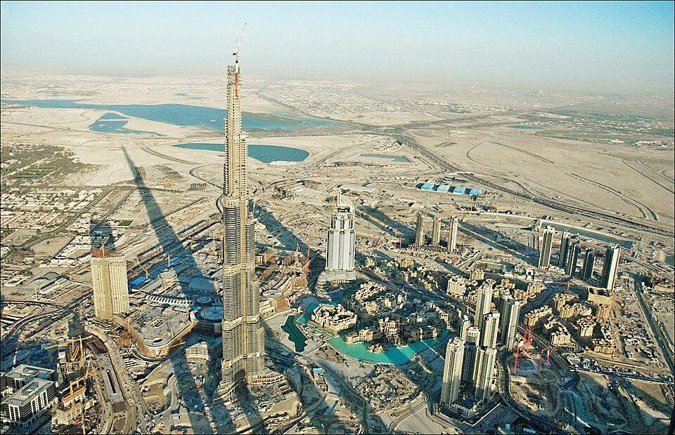
1.2 The Burj Khalifa: The Buttressed Core and the Limits of Concrete
The Burj Khalifa is the global structural masterpiece that defined supertall engineering. Its height, 828 metres, was kept secret until its opening on 4 January 2010; Taipei 101 at 509 metres had been surpassed by 319 metres, a margin that reflected a structural system that broke the paradigm of how supertall iconic engineering structures could be organised.
Burj Khalifa: Technical Data
| Parameter | Value |
| Total height | 828 m (163 floors) |
| Occupied floors | 160 |
| Structural system | Buttressed hexagonal reinforced concrete core |
| Foundation | 3.7 m RC mat + 192 bored piles, 1.5 m dia., 50 m deep |
| Concrete pump height | 600+ m (world record at time of construction) |
| Wind tunnel tests | 17 configurations tested |
| Peak electrical demand | 36 MW |
| Water delivery | 946,000 litres/day |
| Construction duration | 6 years; 22 million man-hours |
| Opened | 4 January 2010 |
| Structural engineer | Bill Baker, Skidmore, Owings & Merrill (SOM) |
The buttressed core system works through a Y-shaped plan: three wings extending from a central hexagonal core, each wing bracing the others. The hexagonal geometry produces an I-section profile, maximising resistance to bending under lateral loads without adding material. The spiralling floor-plate setbacks reduce wind pressure at altitude and, critically, disrupt vortex shedding: the building sheds wind energy at different frequencies at different heights, preventing the resonance that would otherwise accumulate in a uniform shaft. Skidmore, Owings & Merrill (SOM) ran 17 wind tunnel configurations before fixing the geometry.
Dubai’s sandy, sulphate-laden ground required 192 bored piles, 50 metres deep, beneath a 3.7-metre reinforced concrete mat. The concrete mix used water-to-cement ratios below 0.30 and chilled water in place of mixing water during summer to prevent premature hydration at altitude. Concrete was pumped to over 600 metres in a single stage.
The buttressed core is among the iconic structures that shaped modern engineering most directly in the twenty-first century: not the Burj Khalifa itself but the structural system it introduced. The buttressed core has since been adopted in every supertall. It is the Burj Khalifa’s primary legacy. The Council on Tall Buildings and Urban Habitat holds the building’s technical record as the global reference for supertall structural benchmarking.
2. Bridges: Spanning the Impossible
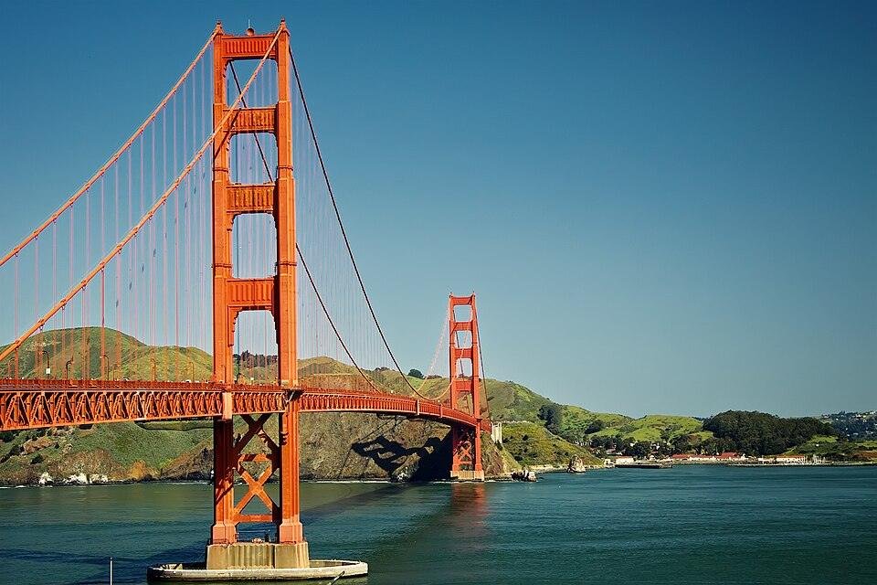
A suspension bridge converts traffic weight and wind into cable tension, then anchors that tension in the ground. The Golden Gate Bridge is among the most instructive famous architectural and engineering landmarks in the discipline: not only for what it got right but for the failure it indirectly caused, the Tacoma Narrows collapse of 1940, which understanding the Golden Gate requires understanding too.
2.1 The Golden Gate Bridge: Suspension Engineering and the Science of Wind
The detailed account of the Golden Bridge’s structural decisions that shaped this iconic bridge shows how much of the engineering was settled not in the boardroom but in the calculations.
Golden Gate Bridge: Technical Data
| Parameter | Value |
| Main span | 4,200 ft (1,280 m) |
| Total length | 8,981 ft (2,737 m) |
| Tower height above roadway | 500 ft (152 m) |
| Tower height above water | 746 ft (227 m) |
| Cable diameter | 92.7 cm |
| Individual wires per cable | 27,572 |
| Anchorage tension capacity | 63 million lbs per anchorage |
| Deck clearance (mid-span) | 67 m above mean high water |
| Total structure weight | 887,000 tonnes |
| Stiffening truss bracing | 4,700 tonnes |
| Opened | 27 May 1937 |
| Seismic retrofit program | 4 phases; current budget approaching USD $1 billion |
Moisseiff’s deflection theory held that a suspension bridge deck’s own weight helped stabilise it under lateral loads, permitting a lighter, more flexible structure. Applied correctly, it produced one of the twentieth century’s most famous engineering marvels. Applied beyond its valid range, it produced the Tacoma Narrows collapse, allowing a lighter, more flexible structure than conservative practice required.
Applied to the Golden Gate’s 4,200-foot main span, the theory produced a deck that was both economical and structurally sound. Applied three years later to the Tacoma Narrows Bridge, with a narrower deck and less stiffening mass, it produced torsional flutter at 64 km/h and the bridge’s collapse on 7 November 1940. Moisseiff’s theory was not wrong for the Golden Gate; it was over-generalised. The failure created the field of aeroelastic bridge analysis.
The Golden Gate Bridge is among the global structural masterpieces that matter as much for what they got wrong as for what they got right. The two main cables each contain 27,572 wires, with each anchorage resisting 63 million pounds of tension. The towers are hollow steel cells, designed to minimise wind resistance while carrying the vertical compression from the cables. The deck’s stiffening trusses add 4,700 tonnes of resistance against oscillation. The total structure weighs 887,000 tonnes.
World engineering landmarks are maintained, not just admired. The Golden Gate Bridge’s ongoing active seismic retrofit confirms that distinction precisely: they continue to serve and be invested in, not simply admired. The Golden Gate Bridge, Highway and Transportation District publishes the full specifications and retrofit documentation.
Further Reading: Golden Gate Bridge: Stunning Engineering Genius Across San Francisco Bay
3. Performing Arts Venues: When Architecture Becomes Structural Argument
A concert hall must function as both an acoustic instrument and a structural system simultaneously, and those two requirements pull in opposite directions. In the four iconic engineering structures examined here, that collision produced four distinct structural responses: a decade of geometric dead ends resolved by a sphere, a 60-degree climate range handled by a thermally compensated curtain wall, a column-free hall inside a curved steel hull, and a mirror-clad desert box that structurally cannot move.
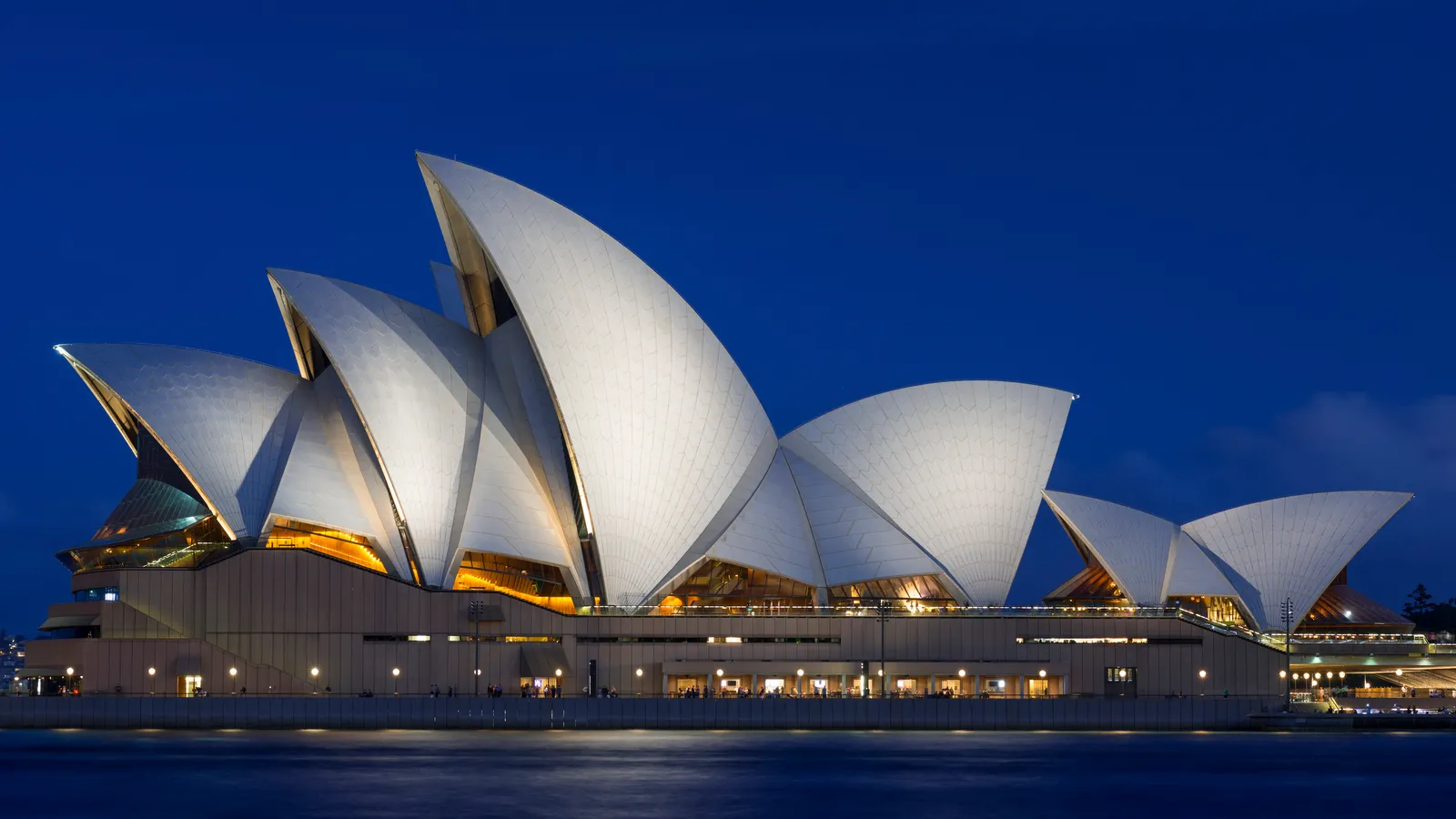
3.1 The Sydney Opera House: Geometry as Engineering Solution
Jørn Utzon won the 1957 Sydney Opera House competition with sweeping shell-shaped roofs and no constructible geometry behind them. The complete technical account of the structural engineering behind this building is the story of what happened over the next four years.
Sydney Opera House: Technical Data
| Parameter | Value |
| Roof shells | 10 (derived from a single sphere) |
| Precast concrete ribs | 2,194 |
| Ceramic roof tiles | 1,056,006 |
| Concrete piers | 588 (to 25 m below sea level) |
| Site area | 1.8 hectares |
| Construction stages | 3 (1959–1973) |
| Final construction cost | AUD $102 million |
| Original estimate | AUD $7 million |
| Annual economic contribution | AUD $775+ million (NSW economy) |
| Annual visitors | 1.5+ million |
| Designer | Jørn Utzon; structural engineer: Ove Arup & Partners |
What followed Utzon’s appointment was four years of failed geometry, the most instructive period in the history of iconic architecture, because it showed how completely a structural problem can resist engineering effort when the right insight has not yet arrived. The engineering team at Ove Arup & Partners attempted at least twelve approaches. The fundamental problem was that each shell had a different curvature, meaning ten different sets of formwork and ten different structural solutions.
At least twelve geometric approaches were tried and rejected between 1957 and 1961. The construction started in 1959 anyway, on the podium, because the government was impatient. Those early podium columns had to be demolished and rebuilt when the shell geometry was finally resolved because they had been sized for a structure that no longer existed.
The resolution came in late 1961. The spherical solution was an architectural engineering achievement in geometric reasoning as much as in structural engineering: a single insight that dissolved a problem four years of analysis had not cracked. Utzon realised that all ten shells could be cut from the surface of a single sphere. He demonstrated it by peeling sections from an orange. Every arch, regardless of size, shared the same radius of curvature, meaning all 2,194 precast concrete ribs could be cast from a common mould. The formwork problem dissolved. The shells were constructed from those ribs, clad in 1,056,006 ceramic tiles on 588 concrete piers driven to 25 metres below sea level.
The project cost AUD$102 million, against an estimate of AUD$7 million, and took 14 years instead of 4. The computational methods developed for its shells served as the foundation for parametric structural design. The Sydney Opera House Trust archives document the full engineering history. The building received UNESCO World Heritage status in 2007, recognised as an outstanding example of twentieth-century architectural engineering.
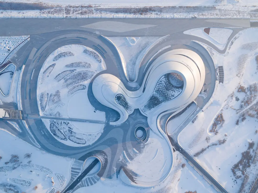
3.2 The Harbin Opera House: Landscape-Integrated Structural Form
MAD Architects won the competition for the Harbin Opera House with a concept that reads, from the air, like a landscape feature rather than a building. The 79,000-square-metre complex rises from the Songhua River floodplain as continuous curves without a single right angle: no standard floor plates, no repeating geometry, and a façade system required to perform across a 60-degree annual temperature range.
Harbin Opera House: Technical Data
| Parameter | Value |
| Total GFA | 79,000 m² |
| Grand Theatre seating capacity | 1,600 |
| Music Hall seating capacity | 400 |
| Annual temperature range | −30°C (winter) to +30°C (summer) = 60°C swing |
| Façade system | Aluminium panels + glass curtain wall (thermal expansion-rated) |
| Structural frame | Combined steel and concrete, free-form geometry |
| Snow load classification | Among the highest in China |
| Location | Songhua River Cultural Island, Harbin, China |
| Completed | 2015 |
| Architect | MAD Architects (Ma Yansong) |
Harbin sits in Heilongjiang Province, where January temperatures regularly drop to -30 °C and July temperatures reach 30 °C. That 60-degree annual swing imposes thermal movement on every exposed component. The aluminium and glass curtain wall system was calibrated specifically for that range, with expansion joints and cladding fixings designed to absorb movement without breaking the weathertight seal. The structural frame, a combination of steel and concrete shaped to follow the free-form geometry, carries snow loads that rank among the most demanding in China while maintaining the unbroken curvilinear surfaces the design requires.
The Harbin Opera House is one of the iconic structures that shaped modern engineering thinking about climate-integrated façade design. The integration of building and terrain is one of the more unusual architectural engineering achievements of the past decade. The building’s public roof terraces function as both structural and civic elements: they distribute loads across the building’s footprint while connecting the complex to the wetland ecology of the floodplain. The World Architecture Festival shortlisted it among the decade’s famous engineering marvels for how large cultural buildings can treat climate and landscape as structural parameters rather than obstacles to be overcome.
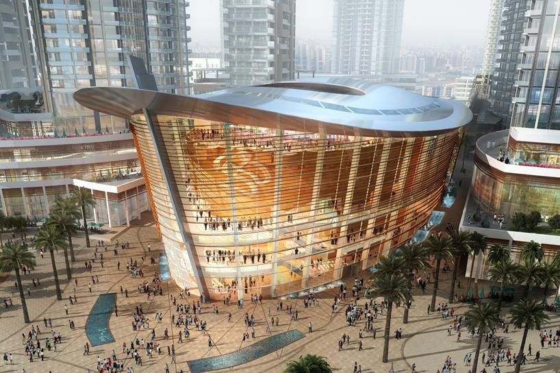
3.3 The Dubai Opera House: Steel Geometry in a Desert Cultural Hub
The Dubai Opera House opened in 2016 in Downtown Dubai, 300 metres from the Burj Khalifa. The brief demanded a 2,000-seat multi-format venue that could convert between theatre, concert hall, and flat-floor configuration, all inside a building shaped like a dhow. The dhow form was not decorative; it was structural. A curved hull profile distributes lateral loads efficiently along its length, and the absence of flat vertical faces reduces wind pressure from the Gulf’s periodic shamal storms.
Dubai Opera House: Technical Data
| Parameter | Value |
| Seating capacity | 2,000 |
| Structural form | Long-span steel frame, dhow-inspired curved profile |
| Performance formats | Theatre, concert hall, flat-floor (transformable) |
| Location | Downtown Dubai, adjacent to Burj Khalifa and Dubai Fountain |
| Façade | Perforated cladding panels + glass (solar gain management) |
| Structural challenge | Column-free performance volumes within a curved envelope |
| Opened | 2016 |
| Developer | Dubai Opera District (Emaar Properties) |
The performance volumes are column-free: no internal supports interrupt the sightlines or acoustic geometry of the halls. Achieving that in a building with a curved external profile required transfer structures at roof level to redirect loads around the open spans. The façade uses perforated cladding panels calibrated to manage solar gain while maintaining visual transparency toward the Burj Khalifa and the Dubai Fountain, a relationship the building’s orientation was specifically set to exploit. Building form and structural logic operate here as a single integrated decision, not as competing priorities. The Dubai Opera House is an example of iconic architecture in which the visual form is the structural argument.
Further Reading: Dubai Opera House: Spectacular Structural and Acoustic Engineering in a Desert Megacity
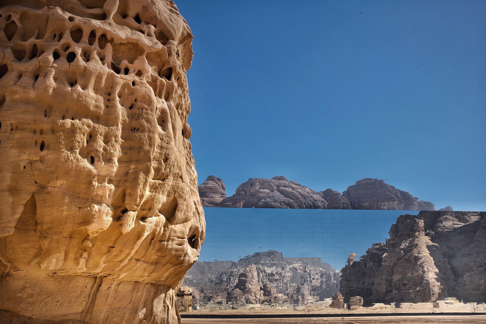
3.4 The Maraya Concert Hall: Mirror Cladding as Structural Discipline
The Maraya Concert Hall sits in the Ashar Valley of AlUla, in the northwest of Saudi Arabia, surrounded by sandstone canyons and Nabataean rock tombs. The building holds the Guinness World Record for the world’s largest mirrored structure: 9,740 square metres of mirror-finish stainless steel on all four facades, reflecting the canyon and the sky back at anyone standing in front of it. The engineering problem was that a mirror-clad building cannot move.
Maraya Concert Hall: Technical Data
| Parameter | Value |
| Mirrored façade area | 9,740 m² (Guinness World Record: largest mirrored building) |
| Seating capacity | 500 |
| Cladding material | Mirror-finish stainless steel panels |
| Structural challenge | Sub-millimetre deflection control across the full façade extent |
| Desert conditions | Sand abrasion, UV degradation, thermal cycling |
| Location | AlUla, Medina Region, Saudi Arabia |
| Completed | 2019 |
| Client | Royal Commission for AlUla (RCU) |
The Maraya Concert Hall’s cladding system is an architectural engineering achievement as much as a structural one, and one of the more unusual in the realm of façade engineering: it demanded that two separate disciplines, structural and façade, work simultaneously to sub-millimetre tolerances. It required the engineering and fabrication disciplines to work to the same millimetre tolerances simultaneously. Any structural deflection produces a visible distortion in the reflection. Tolerances were set in millimetres, requiring a steel frame specified for minimum thermal deflection and fixings that absorb movement without transmitting it to the mirror surface.
The Royal Commission for AlUla is extending the AlUla cultural programme beyond Maraya. The cladding and environmental performance systems developed for this building are the active reference for the next phase of construction.
4. Water Infrastructure: Force, Mass, and the Long Game
Water infrastructure performs in binary over a design life measured in centuries: it holds, or it fails. The two iconic engineering structures here are global structural masterpieces because the construction methods they pioneered became universal practice.
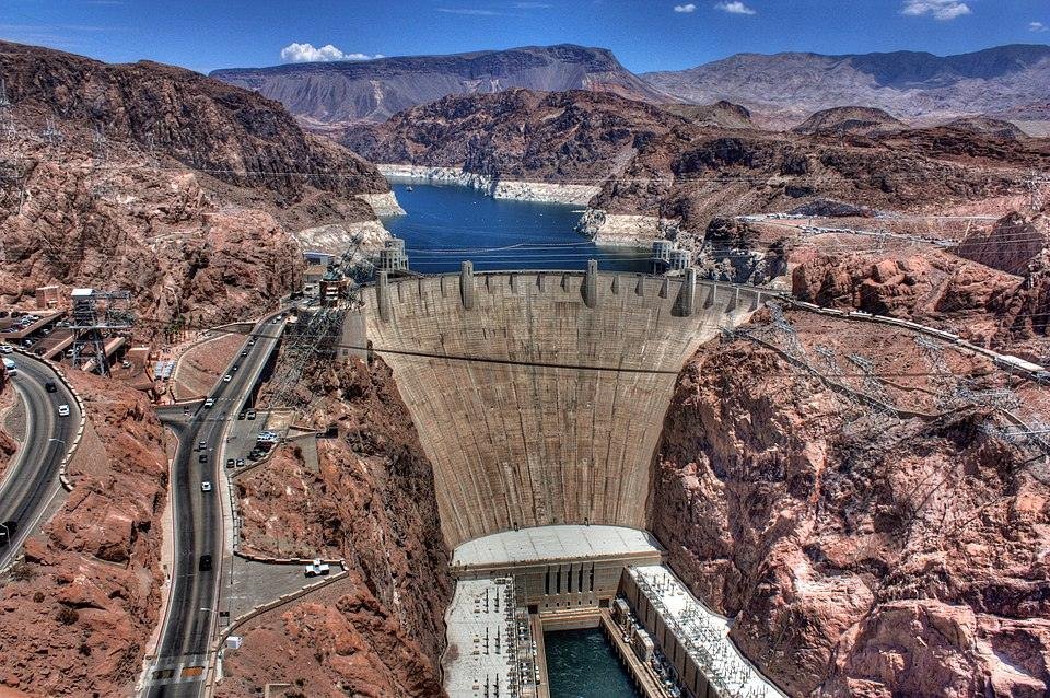
4.1 Hoover Dam: The Arch-Gravity Solution and the Heat Problem
Hoover Dam is the clearest case of what the engineering behind iconic structures produces: a construction method that became a universal practice. In August 1931, the first concrete was poured at Black Canyon on the Nevada-Arizona border. The Bureau of Reclamation’s engineers had already identified the central technical problem: 3.25 million cubic metres of concrete generates heat as it cures, and if poured as a single mass, the heat would take 125 years to dissipate. The thermal stresses during that 125-year cooling period would crack the dam apart. The full technical account of the Hoover Dam concrete engineering documents how that problem was solved.
Hoover Dam: Technical Data
| Parameter | Value |
| Height above bedrock | 221 m |
| Base thickness | 201 m |
| Crest thickness | 14 m |
| Concrete volume | 3.25 million m³ |
| Structural type | Arch-gravity |
| Cooling pipe system | Embedded pipe network; cold Colorado River water circulated during cure |
| Power output | 17 generators supplying Nevada, Arizona, and California |
| Reservoir | Lake Mead (the largest reservoir in the United States at completion) |
| Construction period | 1931–1935 (2 years ahead of schedule) |
| Peak workforce | 5,251 |
| Structural engineer | Bureau of Reclamation, U.S. Department of the Interior |
The solution was to pour the dam in a matrix of interlocking columns rather than as a monolithic mass, with each column containing embedded pipes through which chilled Colorado River water was circulated. The pipes extracted heat from the concrete as it cured. Once a column had cooled to the required temperature, the pipes were grouted under pressure, making the column structurally continuous with its neighbours. The method worked.
Completed in 1935, two years ahead of schedule, Hoover Dam is an architectural engineering achievement in construction programme management as much as in structural innovation. The pipe-cooling technique is now standard practice for any large-scale concrete pour in a warm climate. It is the reason Hoover Dam belongs among the famous architectural and engineering landmarks that matter as technical contributions rather than visual statements.
The engineering behind iconic arch-gravity structures is particularly legible: the structural logic is visible in their physical form. The arch-gravity structural form transfers the horizontal water pressure from Lake Mead laterally into the canyon walls through arch action, while the structure’s own mass resists overturning through gravity. At its base, the dam is 201 metres thick; at the crest, 14 metres. That tapering is the signature of the arch-gravity type: the base carries the highest hydrostatic load and requires the most material, the crest almost none. The 17 generating units supply electricity to Nevada, Arizona, and California.
The U.S. Bureau of Reclamation has replaced or refurbished all 17 original generating units since 2012 as part of a rolling programme of power plant rehabilitation. The dam is 90 years old and operating at design specification.
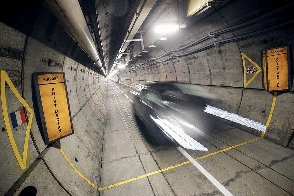
4.2 The Channel Tunnel: Blue Chalk, Boring Machines, and the Geology of Success
Few famous architectural and engineering landmarks have had a longer gestation than the Channel Tunnel, proposed and abandoned more than a dozen times before construction finally began in 1988. The barriers were political and financial, not technical. What made the 1988 attempt different was private finance: the project was funded entirely by Eurotunnel shareholders, with no government money, making it the largest privately financed engineering project in history. That financial structure also meant that cost overruns were borne directly by shareholders’ equity, which focused the engineering team’s attention on getting the geology right.
Channel Tunnel: Technical Data
| Parameter | Value |
| Total length | 50.45 km (Folkestone to Calais terminals) |
| Undersea length | 37.9 km |
| Maximum depth below sea level | 75 m |
| Average depth below the seabed | 45 m |
| Running tunnel diameter | 7.6 m (×2) |
| Service tunnel diameter | 4.8 m (×1) |
| Cross-passages | 270 (at 375 m intervals) |
| UK crossover cavern | 156 m long × 18 m wide × 10 m high (the largest subsea cavern at the time) |
| Precast lining segments | 700,000+ |
| Excavated material (UK side) | 4 million m³ (now Samphire Hoe public park) |
| Opened | May 1994 |
| Procurement model | Privately financed (the largest such project in history at completion) |
The key decision was geological: bore through chalk marl, a pale blue-grey stratum that is impermeable, self-supporting, and consistent across the Channel floor at approximately 40 metres below the seabed. Fractured rock above it would have required continuous waterproofing and ground support; the chalk marl needed neither. Following its elevation changes, it added navigational complexity to the TBMs but eliminated the engineering problems that had defeated every previous attempt.
The Channel Tunnel is one of the global structural masterpieces that earns its status not through aesthetics but through the scale of its engineering ambition and the permanence of its technical contribution. Five TBMs are excavated simultaneously from both ends. Two running tunnels and one service tunnel connect through 270 cross-passages at 375-metre intervals. The 4 million cubic metres of excavated chalk from the British side became Samphire Hoe, a 30-hectare public park below the White Cliffs of Dover.
The Eurotunnel Group technical operations archive documents the tunnel’s current operating statistics. It carries approximately 21 million passengers annually and has operated continuously, with planned maintenance closures, since 1994.
5. Architectural Engineering Achievements: Structures That Redefined Context
Most large buildings are placed on their sites. The global structural masterpieces in this final category begin with a different question: not where to place the building, but what the site itself demands. They are among the famous architectural and engineering landmarks that redefined what a difficult site could become: not where to place the building, but what the site itself demands. The site is cleared, levelled, and treated as a neutral platform.
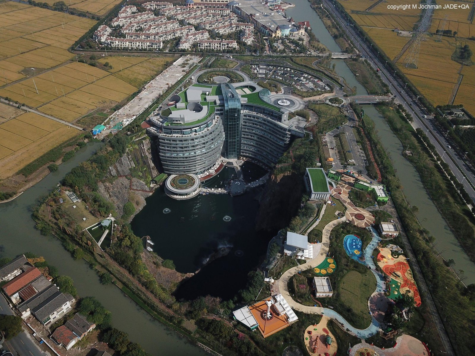
The Intercontinental Shanghai Wonderland Hotel, one of the most unusual iconic engineering structures of the twenty-first century, did the opposite. The site was an 88-metre quarry pit left by decades of stone extraction in Songjiang. The engineering team used it rather than filling it, producing one of the most famous architectural and engineering landmarks of the twenty-first century: a hotel built downward, with two floors submerged in the quarry’s natural lake.
5.1 The Intercontinental Shanghai Wonderland Hotel: Engineering Below Ground
The Intercontinental Shanghai Wonderland Hotel opened in 2018. Its 18 storeys extend 16 floors below the quarry rim and 2 floors into the lake at the quarry base. The vertical rock faces on all sides are not a backdrop; they are a structural boundary that must be monitored, stabilised, and managed as a live geological condition. The building’s relationship to its containment is the central engineering problem.
Intercontinental Shanghai Wonderland Hotel: Technical Data
| Parameter | Value |
| Quarry pit depth | 88 m below original ground level |
| Floors below the quarry rim | 16 |
| Underwater floors | 2 (aquarium suite; hydrostatic pressure management system) |
| Total hotel storeys | 18 |
| Structural system | Rock anchors + waterproof RC retaining walls + watertight basement |
| Geotechnical challenges | Water ingress, seismic activity, vertical rock face instability |
| Façade orientation | Faces quarry rock wall (treated as architectural backdrop) |
| Location | Songjiang District, Shanghai, China |
| Opened | 2018 |
| Architect | Jade + QA International Consultants; ATKINS (structural) |
The Shanghai Wonderland Hotel is among the famous engineering marvels of the 2010s precisely because it solved a problem that had never been formally posed: how to build a full-service hotel inside a live quarry void with vertical rock faces on all sides. Rock anchors tie the retaining structure back into the quarry walls, resisting lateral earth and water pressure. Waterproof reinforced concrete retaining walls line the pit perimeter, and a watertight basement system manages groundwater ingress at the building’s lower levels.
The two submerged floors of the 5-star hotel presented an additional challenge: hydrostatic pressure from the lake acts continuously against the underwater structure’s external face. The management system balances that pressure against the building’s own weight and the anchor system, maintaining structural equilibrium in a condition that varies with lake level and seasonal water-table fluctuations.
The Shanghai Wonderland Hotel is now cited as one of the most technically instructive and famous architectural and engineering landmarks in the adaptive reuse category, not simply for what it achieved, but for the monitoring and management systems it put in place to sustain that achievement. Songjiang is seismically active; the structure must perform under dynamic loading while surrounded by rock faces that could be mobilised by a significant earthquake originating in neighbouring provinces, and the geotechnical monitoring systems installed during construction must remain active. The hotel’s engineering legacy is that former industrial quarries are viable building sites, a proof-of-concept that is shaping adaptive reuse planning across China and Europe.
The Songjiang project stands as an architectural engineering achievement whose significance grows with time, as adaptive reuse becomes a central strategy in responsible construction. It received the International Hotel Awards in 2019 and was recognised by the International Federation of Consulting Engineers as a benchmark for structural design in constrained and degraded site conditions.
Further Reading: InterContinental Shanghai Wonderland: Astonishing Hotel Engineering Inside a Cliff Face
The Technical Block: Engineering Principles Across Iconic Structures
The same three principles run through all ten iconic engineering structures: material choice pushed beyond established limits, load paths unambiguous from first principles, and construction programmes that accepted technical uncertainty. Where any was abandoned, the project failed or came close.
Material Innovation as the Enabling Condition
Eiffel chose wrought iron even though every large structure before him was stone. SOM formulated concrete for pumping to 600 metres in a desert climate. The Maraya team specified mirror-finish stainless steel to millimetre deflection tolerances in a desert environment. In each case, the material decision came before the structural system was resolved; the material made the system possible.
The engineering behind iconic structures follows a consistent sequence: understand the material’s true limits, then design the system around them. The engineering behind iconic structures is inseparable from the materials science that enables them. Every iconic engineering structure here demonstrates what a specific material can achieve at that limit.
Material Innovation by Structure: Comparative Summary
| Structure | Primary Material Innovation | Industry Legacy |
| Eiffel Tower | Wrought iron at unprecedented scale; prefabricated off-site assembly | Template for modern steel fabrication and erection methodology |
| Burj Khalifa | Climate-adapted high-performance concrete; pump delivery at 600 m+ | Supertall concrete mix design; buttressed core system adopted globally |
| Golden Gate Bridge | High-strength suspension cable wire; deflection theory application | Aeroelastic bridge analysis (via Tacoma Narrows failure model) |
| Sydney Opera House | Precast spherical-section concrete ribs; first computer-modelled curved geometry | Computational structural analysis; parametric design methodology |
| Hoover Dam | Mass concrete with embedded pipe-cooling system | Standard for thermal management in large-scale concrete construction |
| Channel Tunnel | 700,000+ precision precast lining segments; chalk marl geology selection | Undersea tunnel geological targeting; TBM navigation at scale |
| Maraya Concert Hall | Mirror-finish stainless steel cladding to sub-mm deflection tolerance | High-spec façade systems in extreme desert conditions |
| Harbin Opera House | Thermally compensated aluminium/glass curtain wall for 60°C annual range | Façade engineering for extreme climate cycling in free-form geometry |
Structural Systems and Load-Path Clarity
Every failure in this article was a load-path failure: Sydney Opera House podium columns sized before the shell loads were calculated, the Tacoma Narrows deck without the mass to resist torsional flutter. The error in both cases was not material; it was the understanding of how forces moved.
The iconic structures that shaped modern engineering are defined, structurally, by load-path clarity from the first design decision. The Eiffel Tower’s parabolic legs trace the wind load path to the foundations. The Burj Khalifa’s Y-plan ensures that lateral loads from any wind direction find a direct path to the hexagonal core. The Sydney Opera House’s spherical shells carry gravity and wind loads through compression in the precast ribs to the podium piers. Hoover Dam’s arch-gravity hybrid splits the hydrostatic load between canyon-wall transfer and mass resistance, with each mechanism contributing to the overall structural response. In each case, the structural system is the physical load path.
Structural System Classification: Ten Iconic Structures
| Structure | Primary Structural System | Critical Load Path |
| Eiffel Tower | Lattice wrought-iron frame | Wind loads → parabolic leg compression → foundations |
| Burj Khalifa | Buttressed hexagonal RC core + Y-plan wings | Lateral loads → wing buttressing → hexagonal core → mat foundation |
| Golden Gate Bridge | Suspension (main cable + stiffening truss) | Live + wind loads → deck → cables → towers → anchorages |
| Sydney Opera House | Precast spherical-section concrete shell arches | Shell gravity + wind → rib compression → podium piers → pile foundations |
| Hoover Dam | Arch-gravity composite | Hydrostatic pressure → arch transfer to canyon walls + gravity mass resistance |
| Channel Tunnel | Segmental precast concrete lining ring | Ground and hydrostatic pressure → ring compression → segment joints |
| Maraya Concert Hall | Steel frame (deflection-controlled) | Wind + thermal → steel frame → foundations; cladding isolated from frame deflection |
| Harbin Opera House | Combined steel-concrete free-form frame | Gravity + snow + wind → composite frame → pile foundations |
| Dubai Opera House | Long-span steel frame with roof transfer structure | Performance volume loads → transfer beams → perimeter steel frame → columns |
| Shanghai Wonderland | Rock-anchored RC retaining structure + watertight basement | Lateral rock pressure + hydrostatic → retaining wall → rock anchor system |
Construction Programme and the Management of Uncertainty
The Sydney Opera House broke ground without a constructible shell geometry. Hoover Dam poured concrete before the cooling system had been tested at scale. In each case, the team solved the problem while building the solution. Eiffel’s structural calculations were analytical, not empirical: the tower had never been built before, and there was no test data for a wrought-iron lattice of this height under dynamic wind loading.
In each case, the engineering team was solving the problem while building the solution. Modern project management theory classifies this as high-risk. The historical record shows it is also the only way to build structures that advance the profession rather than merely repeat it. For a technical examination of how structural systems and design philosophy combine in long-lasting structures, the Construction Frontier’s assessment of how iconic structures are engineered to last provides the analytical framework.
The cost records of global structural masterpieces are not flattering, but they are honest. The iconic engineering structures that most durably shaped modern engineering are not clustered in the overrun column. The overrun data is instructive. The Sydney Opera House cost 14 times its estimate; the Channel Tunnel twice. Hoover Dam, the Golden Gate, the Eiffel Tower, and the Burj Khalifa came in on budget. The correlation is not between iconic status and overrun but between novel structural problems and cost uncertainty.
Cost vs. Estimate Overrun: Selected Structures
| Structure | Original Estimate | Final Cost/Overrun |
| Sydney Opera House | AUD $7 million | AUD $102 million (+1,357%) |
| Channel Tunnel | GBP £4.87 billion | GBP £9.5 billion (+95%) |
| Hoover Dam | USD $49 million | USD $49 million (on budget, 2 years early) |
| Golden Gate Bridge | USD $35 million | USD $35 million (on budget) |
| Burj Khalifa | Est. USD $1.5 billion | USD $1.5 billion (within estimate) |
| Eiffel Tower | 7.8 million francs | 7.8 million francs (within estimate) |
Further Reading: How Iconic Structures Are Engineered to Last: Advanced Materials, Structural Systems, and Design Philosophy
The Next Generation of Iconic Engineering Structures
The world’s most iconic engineering structures of the next decade are being designed now. Saudi Arabia’s Vision 2030 programme has produced a pipeline of iconic engineering structures with no precedent in the existing technical literature: NEOM’s The Line, a 170-kilometre linear city with a continuous 500-metre-high mirror-clad envelope; Diriyah Gate, a heritage district built at urban scale in mudbrick vernacular; and a further sequence of cultural venues in AlUla’s sandstone canyon environment. Each presents structural problems for which the current literature provides partial answers at best.
Africa’s infrastructure pipeline contains iconic engineering structures that will be judged by the same standard as everything in this article. The Grand Inga Dam in the Democratic Republic of Congo, if completed, would become the largest hydropower installation in history. East Africa’s Standard Gauge Railway extensions are generating new solutions for bridge foundations in volcanic rock and lacustrine sediment. The Tanzam Highway upgrade programmes are developing geotechnical methodologies for laterite and black cotton soil conditions that will feed into the global literature on tropical road engineering.
Africa and the Gulf are now building the world’s next-generation engineering landmarks, under conditions of political and technical complexity that parallel those of the projects examined in this article. The global structural masterpieces of the 2030s and 2040s will be recognised not because they are the tallest or the longest. They will be recognised because they solved a structural problem that had not been solved before and then demonstrated that solution reliably over decades of service. Famous iconic engineering structures and marvels are not self-declared but are recognised when the profession adopts their methods. That is the only criterion that has ever actually mattered, and it has never changed.
Conclusion: Why Iconic Structures Define the Discipline
None of the ten iconic engineering structures in this article was built to be iconic. The Eiffel Tower was a temporary fair installation. The Sydney Opera House was budgeted at AUD$7 million for a four-year build. The Channel Tunnel had been proposed and shelved thirteen times. What these projects shared was not ambition in the abstract. It was a specific technical problem that had no established solution, an engineering team that refused to stop at the boundary of existing knowledge, and, in most cases, a client or government that held its nerve through the delays and overruns that follow from both.
The distinction between significant engineering structures and merely large projects lies not in dimensions or cost, but in the lasting impact on the profession. Innovations such as the Eiffel Tower’s lattice geometry, the Golden Gate’s aeroelastic analysis from the Tacoma Narrows collapse, the Sydney Opera House’s computational methods, Hoover Dam’s cooling techniques, the Channel Tunnel’s boring strategies, and the Burj Khalifa’s buttressed core have all advanced engineering practices and set standards for future designs.
Famous engineering marvels earn that status through adoption, not recognition. The world engineering landmarks in this article are cited in feasibility studies, taught in structural engineering programmes, and embedded in the design software of projects under construction right now. The architectural engineering achievements they represent are not historical artefacts; they are the active technical foundation of what is being built today. Iconic architecture at this level does not become obsolete. The engineering behind iconic structures does not age the way a height record ages: it compounds, because each generation of engineers inherits and extends it.
These are the iconic structures that shaped modern engineering, and the most precise definition of that category is this: iconic engineering structures whose construction generated knowledge the profession could not afford to ignore.
Explore More of the World’s Greatest Engineering Achievements
The world’s greatest engineering landmarks continue to shape how we design, build, and innovate. Explore more iconic engineering structures, megaprojects, and engineering breakthroughs from around the world with Construction Frontier: Global Mega Projects.